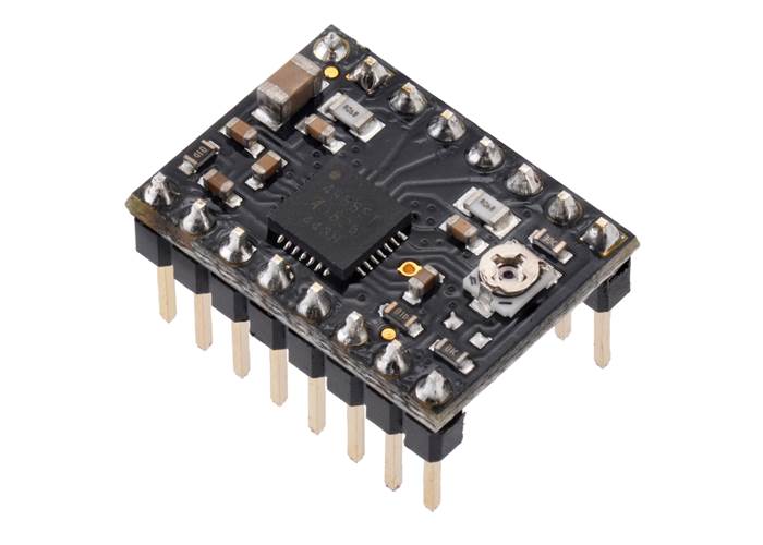
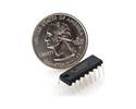
Our Black Edition A4988 stepper motor driver carrier is a higher-performance drop-in replacement for the original A4988 stepper motor driver carrier .
Special Order
Shipping from $4.90
+260 more from our supplier in 7-10 days
Our Code: SKU-003056
Supplier Link: [Pololu MPN:2128]
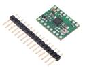
Our Black Edition A4988 stepper motor driver carrier is a higher-performance drop-in replacement for the original A4988 stepper motor driver carrier. It features a four-layer PCB for better thermal performance, allowing the A4988 microstepping bipolar stepper motor driver to deliver approximately 20% more current than our two-layer (green) version. Like our original carrier, the Black Edition offers adjustable current limiting, over-current and over-temperature protection, and five different microstep resolutions. It operates from 8 V to 35 V and can deliver up to 2 A per coil with sufficient additional cooling. This board ships with 0.1″ male header pins included but not soldered in.

A4988 stepper motor driver carrier, Black Edition, bottom view with dimensions.
This product is a carrier board or breakout board for Allegro’s A4988 DMOS Microstepping Driver with Translator and Overcurrent Protection; we therefore recommend careful reading of the A4988 datasheet (1MB pdf) before using this product. This stepper motor driver lets you control one bipolar stepper motor at up to 2 A output current per coil (see the Power Dissipation Considerations section below for more information). Here are some of the driver’s key features:
This product ships with all surface-mount components—including the A4988 driver IC—installed as shown in the product picture.
This product ships individually packaged with 0.1″ male header pins included but not soldered in; we also carry a version with male header pins already soldered in.
The Black Edition has the same component layout and pinout as our A4988 stepper motor driver carrier, so it can be used as a higher-performance drop-in replacement in applications designed for our original drivers. The Black Edition achieves its higher performance through its four-layer printed circuit board (PCB), which better draws heat out of the A4988 driver—while our original carrier can deliver up to approximately 1 A per phase in full-step mode without a heat sink or air flow, the Black Edition can deliver up to approximately 1.2 A under the same conditions.
We also have a variety of other stepper motor driver options in this same form factor with different operating profiles and features.
Some unipolar stepper motors (e.g. those with six or eight leads) can be controlled by this driver as bipolar stepper motors. For more information, please see the frequently asked questions. Unipolar motors with five leads cannot be used with this driver.
The A4988 stepper motor driver carrier comes with one 1×16-pin breakaway 0.1" male header. The headers can be soldered in for use with solderless breadboards or 0.1" female connectors. You can also solder your motor leads and other connections directly to the board. (A version of this board with headers already installed is also available.)
A4988 stepper motor driver carrier, Black Edition, with included hardware. |
Pololu A4988 stepper motor driver carrier, Black Edition, with included header pins soldered. |
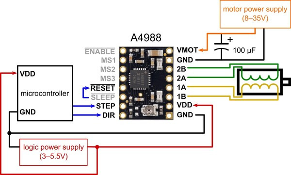 |
Minimal wiring diagram for connecting a microcontroller to an A4988 stepper motor driver carrier (full-step mode). |
|---|
The driver requires a logic supply voltage (3 – 5.5 V) to be connected across the VDD and GND pins and a motor supply voltage (8 – 35 V) to be connected across VMOT and GND. These supplies should have appropriate decoupling capacitors close to the board, and they should be capable of delivering the expected currents (peaks up to 4 A for the motor supply).
Warning: This carrier board uses low-ESR ceramic capacitors, which makes it susceptible to destructive LC voltage spikes, especially when using power leads longer than a few inches. Under the right conditions, these spikes can exceed the 35 V maximum voltage rating for the A4988 and permanently damage the board, even when the motor supply voltage is as low as 12 V. One way to protect the driver from such spikes is to put a large (at least 47 µF) electrolytic capacitor across motor power (VMOT) and ground somewhere close to the board.
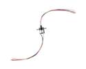
Four, six, and eight-wire stepper motors can be driven by the A4988 if they are properly connected; a FAQ answer explains the proper wirings in detail.
Warning: Connecting or disconnecting a stepper motor while the driver is powered can destroy the driver. (More generally, rewiring anything while it is powered is asking for trouble.)
Stepper motors typically have a step size specification (e.g. 1.8° or 200 steps per revolution), which applies to full steps. A microstepping driver such as the A4988 allows higher resolutions by allowing intermediate step locations, which are achieved by energizing the coils with intermediate current levels. For instance, driving a motor in quarter-step mode will give the 200-step-per-revolution motor 800 microsteps per revolution by using four different current levels.
The resolution (step size) selector inputs (MS1, MS2, and MS3) enable selection from the five step resolutions according to the table below. MS1 and MS3 have internal 100kΩ pull-down resistors and MS2 has an internal 50kΩ pull-down resistor, so leaving these three microstep selection pins disconnected results in full-step mode. For the microstep modes to function correctly, the current limit must be set low enough (see below) so that current limiting gets engaged. Otherwise, the intermediate current levels will not be correctly maintained, and the motor will skip microsteps.
| MS1 | MS2 | MS3 | Microstep Resolution |
|---|---|---|---|
| Low | Low | Low | Full step |
| High | Low | Low | Half step |
| Low | High | Low | Quarter step |
| High | High | Low | Eighth step |
| High | High | High | Sixteenth step |
Each pulse to the STEP input corresponds to one microstep of the stepper motor in the direction selected by the DIR pin. Note that the STEP and DIR pins are not pulled to any particular voltage internally, so you should not leave either of these pins floating in your application. If you just want rotation in a single direction, you can tie DIR directly to VDD or GND. The chip has three different inputs for controlling its many power states: RST, SLP, and EN. For details about these power states, see the datasheet. Please note that the RST pin is floating; if you are not using the pin, you can connect it to the adjacent SLP pin on the PCB to bring it high and enable the board.
One way to maximize stepper motor performance is to use as high of a voltage as is practical for your application. In particular, increasing the voltage generally allows for higher step rates and stepping torque since the current can change more quickly in the coils after each step. However, in order to safely use voltages above the rated voltage of a stepper motor, the coil current must be actively limited to keep it from exceeding the motor’s rated current.
The A4988 supports such active current limiting, and the trimmer potentiometer on the board can be used to set the current limit. One way to set the current limit is to put the driver into full-step mode and measure the current running through a single motor coil while adjusting the current limit potentiometer. This should be done with the motor holding a fixed position (i.e. without clocking the STEP input). Note that the current you are measuring is only 70% of the actual current limit setting, since both coils are always on and limited to this value in full-step mode, so if you later enable microstepping modes, the current through the coils will be able to exceed this measured full-step current by 40% (1/0.7) on certain steps; please take this into account when using this method to set the current limit. Also, note that you will need to perform this adjustment again if you ever change the logic voltage, VDD, since the reference voltage that sets the current limit is a function of VDD.
Note: The coil current can be very different from the power supply current, so you should not use the current measured at the power supply to set the current limit. The appropriate place to put your current meter is in series with one of your stepper motor coils.
Another way to set the current limit is to calculate the reference voltage that corresponds to your desired current limit and then adjust the current limit potentiometer until you measure that voltage on the VREF pin. The VREF pin voltage is accessible on a via that is circled on the bottom silkscreen of the circuit board. The current limit, IMAX, relates to the reference voltage as follows:
``I_(MAX) = (V_(REF)) / (8 * R_(CS))``
or, rearranged to solve for VREF:
``V_(REF) = 8 * I_(MAX) * R_(CS)``
RCS* is the current sense resistance, and all units manufactured since 2017 have 0.068 Ω current sense resistors (units made prior to this had green 0.050 Ω sense resistors). So, for example, if you want to set the current limit to 1 A, you would set VREF to 540 mV. Doing this ensures that even though the current through each coil changes from step to step, the magnitude of the current vector in the stepper motor stays constant at 1 A:
``sqrt(I_(COIL1)^2 + I_(COIL2)^2) = I_(MAX) = 1 text (A)``
If you instead want the current through each coil to be 1 A in full-step mode, you would need to set the current limit to be 40% higher, or 1.4 A, since the coils are limited to approximately 70% of the set current limit in full-step mode (the equation above shows why this is the case). This can be accomplished by setting VREF to 770 mV.
The A4988 driver IC has a maximum current rating of 2 A per coil, but the actual current you can deliver depends on how well you can keep the IC cool. The carrier’s printed circuit board is designed to draw heat out of the IC, but to supply more than approximately 1.2 A per coil, a heat sink or other cooling method is required (in our tests, we were able to deliver approximately 1.4 A per coil with air flow from a PC fan and no heat sink).
This product can get hot enough to burn you long before the chip overheats. Take care when handling this product and other components connected to it.
Please note that measuring the current draw at the power supply will generally not provide an accurate measure of the coil current. Since the input voltage to the driver can be significantly higher than the coil voltage, the measured current on the power supply can be quite a bit lower than the coil current (the driver and coil basically act like a switching step-down power supply). Also, if the supply voltage is very high compared to what the motor needs to achieve the set current, the duty cycle will be very low, which also leads to significant differences between average and RMS currents.
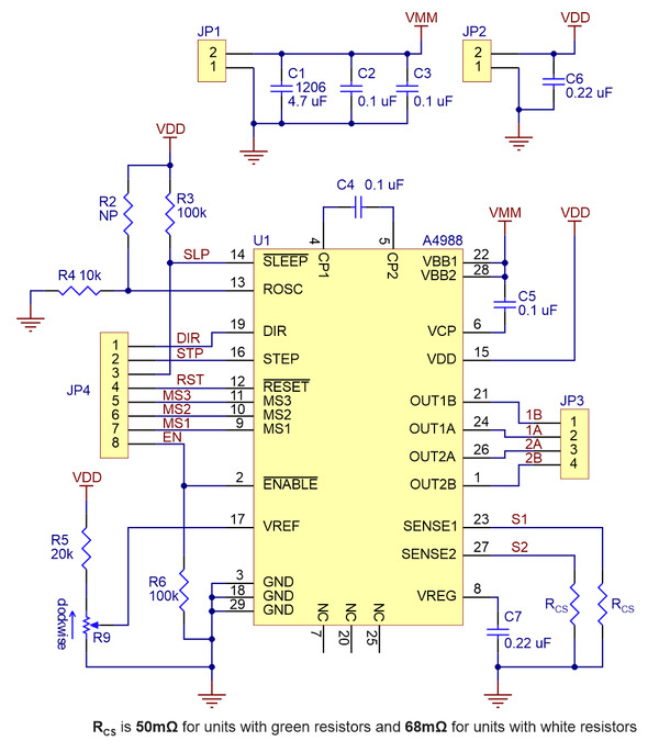 |
Schematic diagram of the A4988 stepper motor driver carrier (both green and black editions). |
|---|
Note: This board is a drop-in replacement for our original A4988 stepper motor driver carrier.
| Size: | 0.6″ × 0.8″ |
|---|---|
| Weight: | 1.5 g1 |
| Minimum operating voltage: | 8 V |
|---|---|
| Maximum operating voltage: | 35 V |
| Continuous current per phase: | 1.2 A2 |
| Maximum current per phase: | 2 A3 |
| Minimum logic voltage: | 3 V |
| Maximum logic voltage: | 5.5 V |
| Microstep resolutions: | full, 1/2, 1/4, 1/8, and 1/16 |
| Reverse voltage protection?: | N |
| Bulk packaged?: | N |
| Header pins soldered?: | N4 |
| PCB dev codes: | md09c |
|---|
This DXF drawing shows the locations of all of the board’s holes. It applies to both the green (md09b) and black (md09c) editions of the A4988 stepper motor driver carrier.
A short video showing the in-house assembly of a panel of Black Edition A4988 stepper motor driver carriers on our Samsung SM421F pick and place machine.
A customer-made module for using the Pololu A4983/A4988 Stepper Motor Driver Carrier in Kicad. By Jared Harvey, October 2011.
This Arduino library, written by forum member laurb9, allows users to control a stepper motor with our A4988, DRV8825, DRV8834, and TB67S581FNG"-based carriers (for the TB67S581FNG, use the library code for the DRV8825 as the TB67S581FNG is Toshiba’s version of the DRV8825). The library has functions that enable users to set rotational rate, change microstepping mode, and specify how many steps to take or specify how many degrees to rotate.
Yes. To avoid damaging your stepper motor, you want to avoid exceeding the rated current, which is 600 mA in this instance. All of our stepper motor drivers let you limit the maximum current, so as long as you set the limit below the rated current, you will be within spec for your motor, even if the voltage exceeds the rated voltage. The voltage rating is just the voltage at which each coil draws the rated current, so the coils of your stepper motor will draw 600 mA at 3.9 V. By using a higher voltage along with active current limiting, the current is able to ramp up faster, which lets you achieve higher step rates than you could using the rated voltage.
If you do want to use a lower motor supply voltage for other reasons, consider using our DRV8834 or STSPIN-220 low-voltage stepper motor drivers.
Yes, you do! Setting the current limit on your stepper motor driver carrier before connecting your motor is essential to making sure that it runs properly. An appropriate current limit also ensures that your motor is not allowed to draw more current than it or your driver can handle, since that is likely to damage one or both of them.
Setting the current limit on this stepper motor driver is done by adjusting the on-board potentiometer. We strongly recommend using a multimeter to measure the VREF voltage while setting the current limit so you can be sure you set it to an appropriate value (just turning the pot randomly until things seem to work is not a good approach). The following video has more details on setting the current limit:
Measuring the current draw at the power supply does not necessarily provide an accurate measure of the coil current. Since the input voltage to the driver can be significantly higher than the coil voltage, the measured current on the power supply can be quite a bit lower than the coil current (the driver and coil basically act like a switching step-down power supply). Also, if the supply voltage is very high compared to what the motor needs to achieve the set current, the duty cycle will be very low, which also leads to significant differences between average and RMS currents: RMS current is what is relevant for power dissipation in the chip but many power supplies won’t show that. You should base your assessment of the coil current on the set current limit or by measuring the actual coil currents.
Please note that while the A4988 driver IC is capable of supplying 2 A per coil, the chip by itself will overheat at lower currents. The carrier board PCB helps draw heat away from the IC, but we have found that it generally requires a heat sink to deliver more than approximately 1 A per coil (the Black Edition A4988 carrier has a four-layer PCB that lets it deliver up to around 1.2 A per coil without a heat sink), but this number depends on factors such as ambient temperature and air flow. For example, sealing three A4988 driver carriers in close proximity in a small box will cause them to overheat at lower currents than a unit by itself in open air.