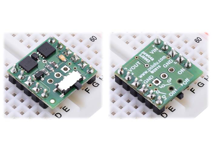
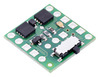
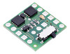
This breadboard-compatible module is an alternative to bulky power switches. It uses a small integrated slide switch to control a high-side power MOSFET that can deliver continuous currents up to around 4 A at 4.5 V to 40 V .
Special Order
Shipping from $4.90
+270 more from our supplier in 7-10 days
Our Code: MCU-60172
Supplier Link: [Pololu MPN:2811]
This breadboard-compatible module is an alternative to bulky power switches. It uses a small integrated slide switch to control a high-side power MOSFET that can deliver continuous currents up to around 4 A at 4.5 V to 40 V. The board features reverse-voltage protection and also makes it easy to control the MOSFET with an external switch or the digital output of a microcontroller.
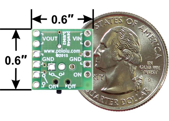
Mini MOSFET Slide Switch with Reverse Voltage Protection, bottom view with dimensions.
This product is a power switch implemented as a pair of P-channel MOSFETs configured as a high-side switch with reverse voltage protection and controlled by a micro slide switch. Because the main current does not go through the controlling mechanical switch, a variety of switches can be used without concern for the current they can carry. For example, a small slide or toggle switch can be mounted conveniently on a control panel with thin wires running to it, while the main power path can be shorter and with thicker wires. Pushbutton or tactile switches can also be used for momentary switching applications.
Unlike the Pololu Pushbutton Power Switches, which can lose their state when power is disconnected and reapplied, the conducting state of the MOSFET Slide Switches is determined only by the physical control switch (or a signal supplied to the “ON” pin), independent of power applied to the board. This can make them more appropriate for applications where the supplied power may be intermittent.
Warning: Do not use this switch as an emergency cutoff or similar safety disconnect in applications where failure to cut power could lead to injury or property damage.
Four versions of the MOSFET slide switches are available:
The two Mini MOSFET Slide Switches are smaller, lower-current versions that are useful for applications with tight size constraints or lower power requirements. Also, the the Mini LV is the only one of the four that works below 4.5 V; since it can operate down to 1.8 V, this version can be used with a single lithium cell battery.
 |
The pinout of the Big version is the same as the pinout of the Mini version with several additional redundant connection points for convenience, including main power connections that are compatible with 5 mm terminal blocks.
The primary functional difference between the each of the units arises from the MOSFET used, which sets the operating range and performance of the units:
 LV |
 SV |
 MP |
 HP |
|
|---|---|---|---|---|
| Absolute max voltage: | 20 V | 40 V | ||
| Recommended operating voltage: | 1.8 V to 16 V | 4.5 V to 32 V | ||
| MOSFET combined on resistance (max) | 26 mΩ @ 1.8 V | |||
| 16 mΩ @ 4.5 V | 90 mΩ @ 4.5 V | 40 mΩ @ 4.5 V | 13 mΩ @ 4.5 V | |
| 50 mΩ @ 10 V | 30 mΩ @ 10 V | 8.6 mΩ @ 10 V | ||
| Continuous current at 55°C(1) | 3.0 A | 2.0 A | 4.0 A | 6.0 A |
| Continuous current at 150°C(1) | 6.0 A | 4.3 A | 8.0 A | 16 A |
| Maximum current | 12 A | 7.2 A | 40 A | 90 A |
| Current consumption in on state(2) | ~210 μA/V | ~65 μA/V | ||
| LED colour | red | green | ||
| Size | 0.6″ × 0.6″ × 0.1″ | 0.8″ × 1.0″ × 0.16″ | ||
| Weight | 0.6 g | 2.7 g | ||
1 At 12 V with ambient temperature of 22°C in still air.
2 On state current is dominated by indicator LED; current is approximately proportional to input voltage.

Pinout diagram of Mini MOSFET Slide Switch with Reverse Voltage Protection.
In the most basic application, power can be applied to the VIN and ground pins, with the on-board mini slide switch controlling power on the VOUT pins. To use an alternate SPST switch to control the MOSFETs, set the on-board slide switch to the off position and connect the alternate switch between ground and the switch control terminal, which is accessible both in the centre of the board and along the side. The following example shows a larger slide switch soldered directly to the three through-hole pins in the centre of the board:
 |
If the physical switch is in the “off” position, the switch state can also be controlled by a digital signal (e.g. from a microcontroller) via the “ON” control pin. Driving the “ON” pin low (or leaving it disconnected) will leave the switch off; driving the pin beyond approximately 1 V will turn the switch on. The maximum voltage for the “ON” pin is 30 V, independent of the switch voltage (VIN).
The MOSFET Slide Switch is compatible with solderless breadboards and perforated circuit boards with standard 0.1″ spacing. For such applications, the included male header pins can be soldered to the switch PCB. Alternatively, wires can be soldered directly to the switch PCB for non-breadboard applications. For high-current applications, make sure that the wires can safely carry the current. Two pads/pins are provided for each of the power nodes, and multiple pads should be used for applications drawing over 5 A.
|
Two possible orientations for using the Mini MOSFET Slide Switch in a breadboard. |
Because MOSFETs in the on state are effectively resistive, the power heating the board is proportional to the square of the current flowing through it. The comparison table near the top of this page shows typical currents that heat the MOSFETs to 55°C, where the MOSFETs start being noticeably warm but are still generally safe to touch, and currents that heat the MOSFETs to 150°C, the absolute limit for the MOSFETs. With adequate cooling, or for brief periods if the MOSFETs are not hot to begin with, currents up to the listed maximums are attainable.
Interrupting large currents can cause voltage spikes (positive on the input side and negative on the output side) that depend on the inductance of the power connections and that can exceed the limits of the device. Appropriate measures to limit the size of these spikes include minimising lengths of wires, placing capacitors at the power switch to smooth the spikes and absorb some of the energy, placing a schottky diode across the power output to absorb negative spikes, and placing a transient voltage suppressor (TVS) across the power input to absorb positive spikes.
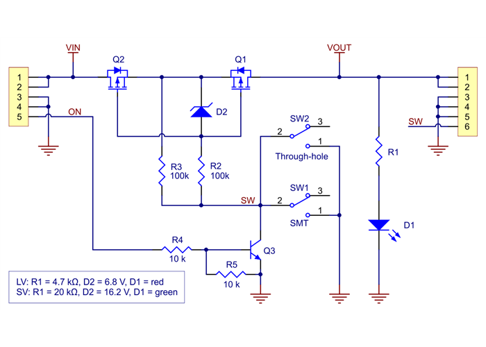
Schematic diagram of the Mini MOSFET Slide Switch with Reverse Voltage Protection.
This diagram is also available as a downloadable PDF (655k pdf).
| Size: | 0.6″ × 0.6″ × 0.1″1 |
|---|---|
| Weight: | 0.6 g2 |
| Current rating: | 4.3 A3 |
|---|---|
| Minimum operating voltage: | 4 V |
| Maximum operating voltage: | 40 V4 |
| Reverse voltage protection?: | Y |
| PCB dev codes: | psw04a |
|---|---|
| Other PCB markings: | 0J8962 |
| LED colour: | green |
Printable schematic diagram of the Mini MOSFET Slide Switch with Reverse Voltage Protection.
This DXF drawing shows the locations of all of the board’s holes.