These small brushed DC gearmotors can deliver a lot of power for their size. This version has a 6V brushed DC motor combined with a 73:1 metal spur gearbox.
Special Order
Shipping from $9.90
+32 more from our supplier in 7-10 days
Our Code: MEC-30084
Supplier Link: [Pololu MPN:1163]
These small brushed DC gearmotors can deliver a lot of power for their size. This version has a 6V brushed DC motor combined with a 73:1 metal spur gearbox. The gearmotor is cylindrical with a diameter of 20 mm, and the D-shaped output shaft is 4 mm in diameter and extends 10.7 mm from the face plate of the gearbox.
Key specs at 6 V: 180 RPM and 250 mA free-run, 60 oz-in (4.3 kg-cm) and 3.2 A stall.
Note: This gearmotor is being replaced by a new version with a slightly different gear ratio and a longer output shaft (the motor portion is unchanged). This short-shaft version will be discontinued when the remaining stock is gone.
New versions available! We have replaced these older short-shaft versions of our 20D mm gearmotors with a much wider assortment of gear ratios that feature longer output shafts. You can find the full selection of these new versions here. The older versions are now only available by large-volume special order. Please contact us for more information.
Note that the following product page is being left here for historical purposes; it has not been updated to reflect our current offering of 20D mm gearmotors.
The 20D mm line of brushed DC gearmotors all have the same dimensions except for the length of the gearbox, and they are intended for use at 6 V. In general, these kinds of motors can run at voltages above and below this nominal voltage, so they should comfortably operate in the 3 – 9 V range. Higher voltages could start negatively affecting the life of the motor, and lower voltages might not be practical. Four different gear ratios are available:
| Gear Ratio | No-Load Speed @ 6 V |
No-Load Current @ 6 V |
Stall Torque @ 6 V |
Stall Current @ 6 V |
|---|---|---|---|---|
| 29:1 | 450 RPM | 250 mA | 25 oz-in | 3.2 A |
| 56:1 | 250 RPM | 250 mA | 45 oz-in | 3.2 A |
| 73:1 | 180 RPM | 250 mA | 60 oz-in | 3.2 A |
| 154:1 | 90 RPM | 250 mA | 120 oz-in | 3.2 A |
Note: Stalling gearmotors can greatly decrease their lifetimes, occasionally resulting in immediate damage to the gearbox. This is especially true for the higher gear ratios, which can generate enough torque to damage themselves. Prolonged stalls (on the order of seconds) can result in thermal damage to the motor windings and brushes.
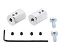
The gearmotor face plate has two mounting holes threaded for M2.5 screws, and you can use our custom-designed 20D mm metal gearmotor bracket (shown in the left picture below) to mount the gearmotor to your project via these mounting holes and the screws that come with the bracket.
Pololu 20D mm gearmotor with bracket and hub. |
White Pololu Wheel 60×8mm on a Pololu 20D mm Metal Gearmotor. |
This gearmotor has an output shaft with a diameter of 4 mm; the Pololu universal aluminium mounting hubs for 4mm shafts can be used to mount our larger Pololu wheels (60mm-, 70mm-, 80mm-, and 90mm-diameter) or custom wheels and mechanisms to the gearmotor’s output shaft (see the right picture above). Alternatively, you could use our 4mm scooter wheel adaptor to mount many common scooter, skateboard, and inline skate wheels to the gearmotor’s output shaft, and you can use our 12mm hex wheel adaptor to use this motor with many common hobby RC wheels. The gearbox’s output shaft also works directly with the 120mm-diameter Wild Thumper wheels, as shown below.
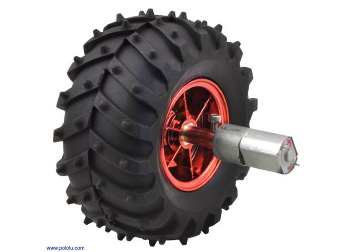
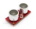
Dagu Wild Thumper wheel 120×60mm (metallic red) with Pololu 20D mm metal gearmotor.
The diagram below shows the dimensions of the 25D mm line of gearmotors (units are mm over [inches]). This diagram is also available as a downloadable PDF (172k pdf).
![Dimensions of the original Pololu 20D mm metal gearmotors with shorter output shafts. Units are mm over [inches]. This diagram only applies to the listed gear ratios.](/cache/files/productimageoriginals/61047_0j7030.1200.jpg)
Dimensions of the original Pololu 20D mm metal gearmotors with shorter output shafts. Units are mm over [inches]. This diagram only applies to the listed gear ratios.
This diagram is also available as a downloadable PDF (172k pdf).
We offer a wide selection of metal gearmotors that offer different combinations of speed and torque. Our metal gearmotor comparison table can help you find the motor that best meets your project’s requirements.
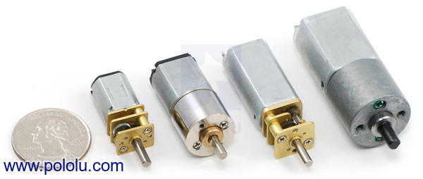 |
Some of the Pololu metal gearmotors. |
|---|
| Size: | 20D x 44L mm |
|---|---|
| Weight: | 43 g |
| Shaft diameter: | 4 mm |
| Gear ratio: | 73:1 |
|---|---|
| No-load speed @ 6V: | 180 rpm |
| No-load current @ 6V: | 250 mA |
| Stall current @ 6V: | 3200 mA |
| Stall torque @ 6V: | 60 oz·in |
Note: This dimension diagram only applies to our older versions with shorter output shafts (gear ratios 29:1, 56:1, 73:1, and 154:1 only).
This file contains 3D models (in the step file format) of the 20D mm gearmotors. Note: these models only accurately represent to our older versions with shorter output shafts (i.e. gear ratios 29:1, 56:1, 73:1, and 154:1).
This MATLAB script, written by Ali Asgher Mansoor Habiby, plots speed, power, current draw, and efficiency as they vary with torque when you input the gearmotor specifications. It also prints the resistance of the motor, and the current draw and torque at which maximum efficiency and maximum power occur.
No; the information we have available for this motor can be found on its product page. However, you can approximate various additional motor parameters from the information found in the “Specs” tab.
The electrical resistance of the motor can be approximated by dividing the rated voltage by the stall current (at the rated voltage). The electromotive force constant (Ke) can be approximated by dividing the rated voltage by the free-run speed (at the rated voltage). To approximate the motor torque constant (Kt), you can divide the stall torque by the stall current.
For pretty much any DC motor, the current, speed, power, and efficiency curves as a function of torque will look like those in the graph below (assuming motor voltage and temperature are constant):
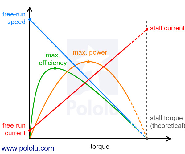 |
The current and speed curves are approximately linear, and the product pages for our motors provide the approximate end points for these lines: (0 torque, no-load current) and (stall torque, stall current) for the red line, and (0 torque, no-load speed) and (stall torque, 0 speed) for the blue line.
The orange output power curve is the product of the speed and the torque, which results in an inverted parabola with its peak at 50% of the stall torque.
The green efficiency curve is the output power divided by the input power, where the input power is current times voltage. The voltage is constant, so you can divide the output power curve by the current line to get the general shape of the efficiency curve, which in turn lets you identify the torque, speed, and current that correspond to max efficiency.
There are many programs out there that you can use to generate these curves. For example, if you have access to MATLAB, you can use this customer-created MATLAB script to generate these motor plots for you from the specifications we provide for each gearmotor.
Note: A good general rule of thumb is to keep the continuous load on a DC motor from exceeding approximately 20% to 30% of the stall torque. Stalling gearmotors can greatly decrease their lifetimes, occasionally resulting in immediate damage to the gearbox or thermal damage to the motor windings or brushes. Do not expect to be able to safely operate a brushed DC gearmotor all the way to stall. The safe operating range will depend on the specifics of the gearmotor itself.


![Dimensions of the original Pololu 20D mm metal gearmotors with shorter output shafts. Units are mm over [inches]. This diagram only applies to the listed gear ratios.](/Cache/Files/ProductImageOriginals/61047_0J7030.1200.jpg?v636600100920371319)