This discrete MOSFET stepper motor driver enables control of one bipolar stepper motor. It supports a wide 8 V to 50 V operating voltage range and can deliver up to 4 A continuous per phase without a heat sink or forced air flow (6 A max with sufficient additional cooling).
In stock in Australia
Shipping from $4.90
+432 more from our supplier in 7-10 days
Our Code: SKU-005566
Supplier Link: [Pololu MPN:3730]
This discrete MOSFET stepper motor driver enables control of one bipolar stepper motor. It supports a wide 8 V to 50 V operating voltage range and can deliver up to 4 A continuous per phase without a heat sink or forced air flow (6 A max with sufficient additional cooling). The SPI interface allows configuration of the current limiting, step mode (9 step modes from full-step through 1/256-step), decay mode, and stall detection. The driver also provides back-EMF feedback that can be used for more advanced control and stall detection algorithms. Additional features include reverse-voltage, under-voltage, and over-current protection.
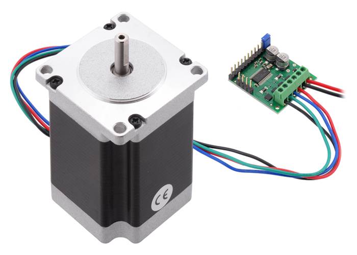
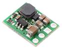
Pololu High-Power Stepper Motor Driver with large stepper motor (36v4 version pictured).

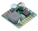
Pololu High-Power Stepper Motor Driver 36v4, bottom view with dimensions.

Pololu High-Power Stepper Motor Driver 36v4, top view.
The Pololu High-Power Stepper Motor Driver 36v4 combines the DRV8711 stepper motor driver IC from Texas Instruments with external MOSFETs to enable control of large bipolar stepper motors at operating voltages from 8 V to 50 V. The DRV8711 has many configurable settings, so please see the DRV8711 datasheet for a detailed explanation of its features and how to use them (we also have an Arduino library that simplifies getting started by providing basic functions for configuring and operating the driver).
The driver’s power performance is a function of the external dual H-bridges, which allow the driver to deliver continuous currents up to 4 A per phase without any additional cooling such as heat sinks or forced air flow. (With sufficient additional cooling, the driver can support currents up to around 6 A per phase; see the Power dissipation considerations section below for more information, including important information about using this product safely.)
We also have a higher-power 36v8 version available with the same dimensions and pinout.
As an alternative to this stepper motor driver, our Tic 36v4 USB Multi-Interface High-Power Stepper Motor Controller has similar power characteristics and offers high-level interfaces (USB, TTL serial, I²C, analogue voltage, quadrature encoder, and RC hobby servo pulses) that make it easier to use for some applications. The Tic’s configuration software allows you to change many of the driver’s settings over USB, eliminating the need to directly use SPI to configure the DRV8711.
19 September 2019 update: We are now shipping a slight revision (md38b) with improved noise and fault tolerance at high input voltages and high current limits.
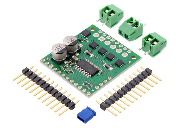
This product ships with all surface-mount components installed as shown in the product picture. However, soldering is required for assembly of the included through-hole parts. The following through-hole parts are included:
The 0.1″ male headers can be broken or cut into smaller pieces as desired and soldered into the smaller through-holes. These headers are compatible with solderless breadboards, 0.1″ female connectors, and our premium and pre-crimped jumper wires. The terminal blocks can be soldered into the larger holes to allow for convenient temporary connections of unterminated power and motor wires (see our short video on terminal block installation). You can also solder your motor leads and other connections directly to the board for the most compact installation.
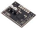
Pololu High-Power Stepper Motor Driver 36v4 with included headers, shorting block, and terminal blocks. |
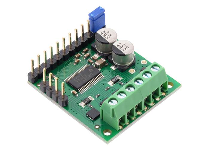
Pololu High-Power Stepper Motor Driver 36v4 with included headers and terminal blocks soldered and shorting block installed. |

Pololu High-Power Stepper Motor Driver 36v4, top view with labeled pinout.
| PIN | Description |
|---|---|
| VIN | 8 V to 50 V board power supply connection (reverse-protected up to 40 V). |
| VM | This pin gives access to the motor power supply after the reverse-voltage protection MOSFET (see the board schematic at the bottom of this page). It can be used to supply reverse-protected power to other components in the system. This pin can also be used with the adjacent GND pin to add an external electrolytic capacitor in systems where additional bypass capacitance would be helpful. |
| GND | Ground connection points for the motor power supply and control ground reference. |
| AOUT1 | Motor output: “positive” end of phase A coil. |
| AOUT2 | Motor output: “negative” end of phase A coil. |
| BOUT1 | Motor output: “positive” end of phase B coil. |
| BOUT2 | Motor output: “negative” end of phase B coil. |
| V5 (OUT) | Regulated 5 V output: this pin gives access to the voltage from the internal regulator of the DRV8711. The regulator can only provide up to 10 mA, so it is primarily only useful for hard-wiring board inputs high and powering pull-ups for the board’s open-drain outputs. It is generally not intended for powering external devices. Note: this 5V output is disabled when the device is in sleep mode. |
| IOREF | All of the board signal outputs (except BEMF) are open-drain outputs that are pulled up to IOREF, so this pin should be supplied with the logic voltage of the controlling system (e.g. 3.3 V for use in 3.3 V systems). For convenience, it can be connected to the neighbouring V5 (OUT) pin when it is being used in a 5 V system. |
| STEP/AIN1 | Changes on this input move the motor current one step up or down in the translator table (even when the motor is disabled). Stepping can also be controlled through the SPI interface, so this pin is optional. In external PWM mode, this pin functions as AIN1 rather than STEP and directly controls the state of the AOUT1 output. |
| DIR/AIN2 | Input that determines the direction of stepper motor rotation. The direction can also be controlled through the SPI interface, so this pin is optional. In external PWM mode, this pin functions as AIN2 rather than DIR and directly controls the state of the AOUT2 output. |
| SDATO | SPI data output. (This pin is also often referred to as “MISO”.) This pin is an open-drain output and is pulled up to IOREF on the board. |
| SDATI | SPI data input. (This pin is also often referred to as “MOSI”.) |
| SCLK | SPI clock input. |
| SCS | SPI chip select input. Logic transitions on this pin are required for SPI communication, even if this is the only device on the SPI bus. |
| SLEEP | By default, the driver pulls this pin low, which puts it in a low-power sleep mode where the motor driver circuitry and the internal 5 V regulator is disabled and all analogue circuitry is placed into a low-power state. The digital circuitry still operates in sleep mode, so the device registers can still be accessed via the serial interface as long as IOREF is externally supplied. This pin must be driven high to enable the device. |
| RESET | Chip reset input. A logic high on this input resets all internal logic, including the indexer and device registers, and disables the driver outputs. Note: the RESET pin does not function while the device is in sleep mode. |
| FAULT | Open-drain output that drives low when an over-current, pre-driver, over-temperature, or under-voltage fault is occurring. This pin is pulled up to IOREF, making it high by default. |
| BIN1 | In external PWM mode, BIN1 directly controls the state of the BOUT1 output. This pin is not used in indexer mode (i.e. when using this device as a stepper motor driver). |
| BIN2 | In external PWM mode, BIN2 directly controls the state of the BOUT2 output. This pin is not used in indexer mode (i.e. when using this device as a stepper motor driver). |
| STALL/BEMFV | Open-drain output that is pulled up to IOREF on the board. In internal stall detect mode, output goes low when stall is detected. In external stall detect mode, output goes low when valid back EMF measurement is available. |
| BEMF | Analogue output that represents the motor back EMF. The signal on this pin can be further processed by a microcontroller to implement more advanced control and stall detection algorithms. |
For more information about these pins, please refer to the DRV8711 datasheet.
At high input voltages (especially above 30 V) and high current limits, the driver’s SPI interface is more likely to be affected by electrical noise from the driver and stepper motor, potentially leading to communication errors. You can reduce this interference with careful wiring and shielding, and you can lower the risk of unexpected behaviour by taking appropriate precautions with SPI communication (for example, read and verify configuration settings after writing them, and avoid configuring the driver while the motor outputs are enabled).
Alternatively, consider using our Tic 36v4 USB Multi-Interface High-Power Stepper Motor Controller, which provides high-level interfaces for configuration and control (making direct SPI communication unnecessary).
Warning: Connecting or disconnecting a stepper motor while the driver is powered can destroy the driver. (More generally, rewiring anything while it is powered is asking for trouble.)
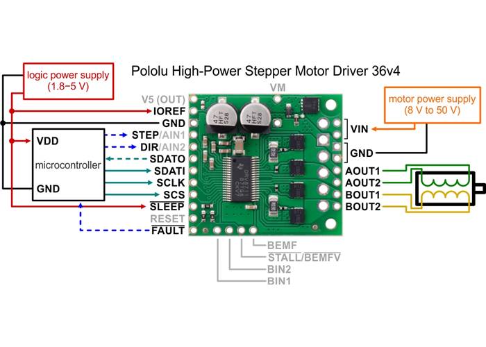
Typical wiring diagram for connecting a microcontroller to a Pololu High-Power Stepper Motor Driver 36v4.
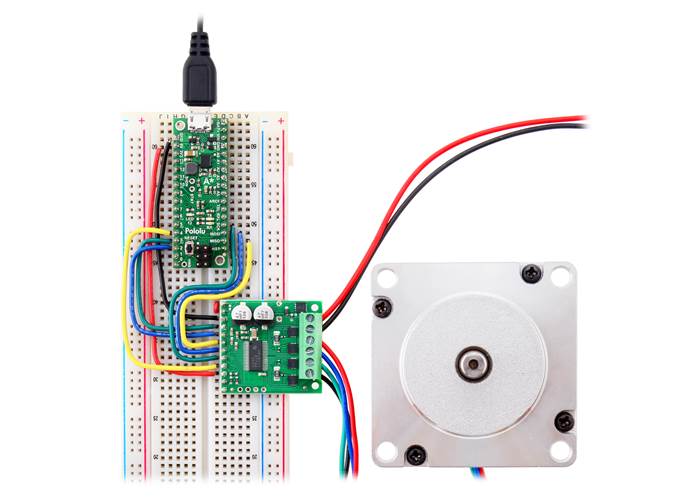
While the High-Power Stepper Motor Driver 36v4 allows control of a stepper motor through a simple step and direction interface, it must first be enabled and configured through its SPI interface after each power-up. This means that the controlling microcontroller must be capable of acting as an SPI master (either with an SPI peripheral or software SPI), and it must be connected to the SDATI, SCLK, and SCS pins. While the SDATO and FAULT pins are not required to use this driver, it is generally a good practice to use them to monitor for error conditions.
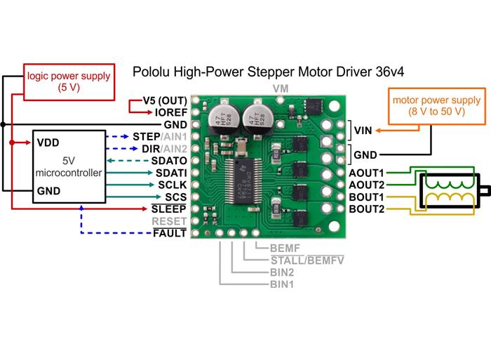
Typical wiring diagram for connecting a microcontroller with a logic voltage of 5 V to a Pololu High-Power Stepper Motor Driver 36v4.
The High-Power Stepper Motor Driver 36v4 has an internal 5 V regulator that can be used to supply IOREF in cases where the board is being used in 5 V systems. We provide a shorting block for connecting V5 to IOREF, or for a more compact connection, you can bridge the surface mount jumper located next to those pins (highlighted in the picture below).
Note that supplying IOREF from V5 does not allow the device registers to be accessed through SPI when the device is in sleep mode, since the V5 regulator output is disabled when SLEEP is low.
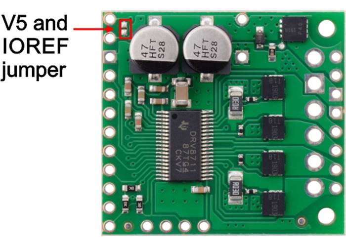
Surface mount jumper for V5 and IOREF pins on the Pololu High-Power Stepper Motor Driver 36v4.
Controlling a Pololu High-Power Stepper Motor Driver with an Arduino-compatible #3104 A-Star 32U4 Mini SV (36v4 version pictured).
We have written a High-Power Stepper Motor Driver library for Arduino that provides basic functions for configuring and operating the driver using an Arduino or Arduino-compatible controller. The library includes several example sketches.
The High-Power Stepper Motor Driver 36v4 can deliver up to 4 A continuous per phase under typical conditions, but the actual current it can deliver will depend on how well you can keep the module cool. The driver’s printed circuit board is designed to draw heat out of the MOSFETs, but performance can be improved by adding a heat sink or forced air flow. (Conversely, performance will be reduced in applications that limit heat dissipation, such as high ambient temperatures or operation in enclosures.) With sufficient additional cooling, the driver can deliver up to 6 A per phase before exceeding the 1 W power ratings of the 30 mΩ current sense resistors.
The driver’s current limit is set through its SPI interface. You can confirm you have set it correctly by using a multimeter to measure the actual current through one of the coils while the stepper motor is in full step mode and not stepping. The current you measure this way will be approximately 70% of the set limit. Please note that measuring the current draw at the power supply will generally not provide an accurate measure of the coil current. Since the input voltage to the driver can be significantly higher than the coil voltage, the measured current on the power supply can be quite a bit lower than the coil current (the driver and coil basically act like a switching step-down power supply). Also, if the supply voltage is very high compared to what the motor needs to achieve the set current, the duty cycle will be very low, which also leads to significant differences between average and RMS currents.
Warning: This motor driver has no meaningful over-temperature shut-off (while the DRV8711 IC has over-temperature protection, it is the external MOSFETs that will overheat first). An over-temperature condition can cause permanent damage to the motor driver. We strongly recommend you do not increase the current limit setting beyond 4 A (or lower in applications with reduced heat dissipation) unless you can first confirm that the temperature of the MOSFETs will stay under 140°C.
Note: When the driver powers up, the current limit setting defaults to the maximum (~18 A). Make sure you set it to something appropriate for both your stepper motor and the driver before activating the outputs!
This product can get hot enough to burn you long before the chip overheats. Take care when handling this product and other components connected to it.

Schematic diagram of the Pololu High-Power Stepper Motor Driver 36v4.
This diagram is also available as a downloadable pdf (117k pdf).
| Size: | 1.3″ × 1.2″ |
|---|---|
| Weight: | 4.9 g1 |
| Minimum operating voltage: | 8 V |
|---|---|
| Maximum operating voltage: | 50 V |
| Continuous current per phase: | 4 A2 |
| Maximum current per phase: | 6 A3 |
| Minimum logic voltage: | 1.5 V |
| Maximum logic voltage: | 5.5 V |
| Microstep resolutions: | full, 1/2, 1/4, 1/8, 1/16, 1/32, 1/64, 1/128, 1/256 |
| Current limit control: | SPI-programmable |
| Reverse voltage protection?: | Y4 |
| Header pins soldered?: | N |
| PCB dev codes: | md38a, md38b |
|---|---|
| Other PCB markings: | 0J12286, 0J12459 |
This file contains 3D models (in the step file format) of the Pololu High Power Stepper Motor Drivers.
This DXF drawing shows the locations of all of the board’s holes.
This library for Arduino makes it easy to interface with Pololu High-Power Stepper Motor Driver 36v4.
Texas Instruments’ product page for the DRV8711 stepper motor gate driver IC, with links to its most up-to-date datasheet, application notes, and other resources.
Yes. To avoid damaging your stepper motor, you want to avoid exceeding the rated current, which is 600 mA in this instance. All of our stepper motor drivers let you limit the maximum current, so as long as you set the limit below the rated current, you will be within spec for your motor, even if the voltage exceeds the rated voltage. The voltage rating is just the voltage at which each coil draws the rated current, so the coils of your stepper motor will draw 600 mA at 3.9 V. By using a higher voltage along with active current limiting, the current is able to ramp up faster, which lets you achieve higher step rates than you could using the rated voltage.
If you do want to use a lower motor supply voltage for other reasons, consider using our DRV8834 or STSPIN-220 low-voltage stepper motor drivers.
Yes, you do! Setting the current limit on your stepper motor driver carrier is essential to making sure that it runs properly. An appropriate current limit also ensures that your motor is not allowed to draw more current than it or your driver can handle, since that is likely to damage one or both of them.
Setting the current limit on the Pololu High-Power Stepper Motor Driver is done through its SPI interface (this is very different from most of our other stepper motor driver carriers, which have their current limits set through their on-board potentiometers). The Pololu High-Power Stepper Motor Driver defaults to its maximum possible current limit setting on start-up, which is much more current than the board can safely deliver, so you will need to set the current limit to an appropriate value for your stepper motor before enabling the driver outputs to prevent damage to the board. This is done by adjusting the TORQUE and ISGAIN bits in the TORQUE and CTRL registers, respectively. The DRV8711 datasheet (1k redirect) has more information on how to set the current limit through the SPI interface, and our Arduino library for the Pololu High-Power Stepper Motor Driver includes example sketches showing how to implement this in software.