This tiny logic level shifter features four bi-directional channels, allowing for safe and easy communication between devices operating at different logic levels.
In stock in Australia
Shipping from $4.90
+496 more from our supplier in 7-10 days
Our Code: SKU-003305
Supplier Link: [Pololu MPN:2595]
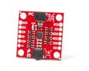
This tiny logic level shifter features four bi-directional channels, allowing for safe and easy communication between devices operating at different logic levels. It can convert signals as low as 1.5 V to as high as 18 V and vice versa, and its four channels are enough to support most common bidirectional and unidirectional digital interfaces, including I²C, SPI, and asynchronous TTL serial.
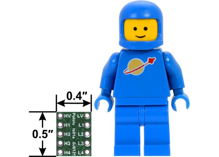
Logic level shifter, 4-channel, bidirectional, bottom view with dimensions next to a LEGO Minifigure for size reference.
As digital devices get smaller and faster, once ubiquitous 5 V logic has given way to ever lower-voltage standards like 3.3 V, 2.5 V, and even 1.8 V, leading to an ecosystem of components that need a little help talking to each other. For example, a 5 V part might fail to read a 3.3 V signal as high, and a 3.3 V part might be damaged by a 5 V signal. This level shifter solves these problems by offering bidirectional voltage translation of up to four independent signals, converting between logic levels as low as 1.5 V on the lower-voltage side and as high as 18 V on the higher-voltage side, and its compact size and breadboard-compatible pin spacing make it easy to integrate into projects.
The logic high levels on each side of the shifter are achieved by 10 kΩ pull-up resistors to their respective supplies; these provide quick enough rise times to allow decent conversion of fast mode (400 kHz) I²C signals or other similarly fast digital interfaces (e.g. SPI or asynchronous TTL serial). External pull-ups can be added to speed up the rise time further at the expense of higher current draw. See the schematic diagram below for more information.
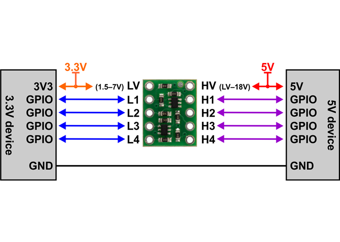
Example wiring diagram for connecting 5 V and 3.3 V devices through the 4-channel bidirectional logic level shifter.
This logic level converter requires two supply voltages: the lower-voltage logic supply (1.5 V to 7 V) connects to the LV pin and the higher-voltage supply (LV to 18 V) connects to the HV pin. The HV supply must be higher than the LV supply for proper operation. Logic low voltages will pass directly from Hx to the corresponding Lx (and vice versa), while logic high voltages will be converted between the HV level to the LV level as the signal passes from Hx to Lx or Lx to Hx.
The level shifter circuit does not require a ground connection to either device, so there are no ground pins on the board. (Some competing level shifter modules provide ground connections that simply act as a pass-through; we have opted to leave these off and make the board smaller.) The two devices being connected through the level shifter must still share a common ground.
The picture below shows a level-shifted TTL serial connection (RX and TX) between a 5 V Arduino Uno and a 3.3 V Raspberry Pi.
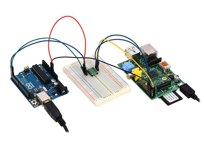
Using the 4-channel bidirectional logic level shifter to create a serial connection between a 5 V Arduino Uno and a 3.3 V Raspberry Pi.
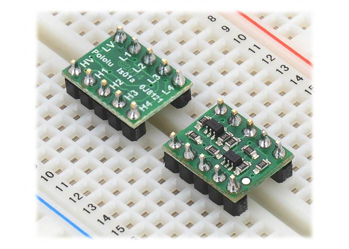
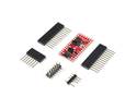
A 0.1″-pitch male header strip is included for use with this board. The strip can be broken into smaller pieces and soldered in so the board can be used with perfboards, breadboards, or 0.1″ female connectors. Alternatively, wires can be soldered directly to the board for more compact installations. The connections are labelled on the back side of the of the PCB, so you might find it more convenient to solder the pins in the way that allows the labelled side to be facing up.
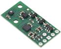
Logic level shifter, 4-channel, bidirectional, with included hardware. |
Logic level shifters in breadboard, one soldered label-side up and the other soldered component-side up. |
The logic level conversion is accomplished with a simple circuit consisting of a single n-channel MOSFET and a pair of 10 kΩ pull-up resistors for each channel. When Lx is driven low, the MOSFET turns on and the zero passes through to Hx. When Hx is driven low, Lx is also driven low through the MOSFET’s body diode, at which point the MOSFET turns on. In all other cases, both Lx and Hx are pulled high to their respective logic supply voltages. External pull-ups can be added to speed up the rise time. This same circuit is detailed in NXP’s application note on I²C bus level-shifting techniques (54k pdf), and we have used it before on carrier boards for 3.3 V sensors with I²C interfaces – like the MinIMU-9 – to enable them to work directly with both 3.3 V and 5 V systems.
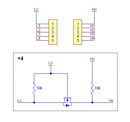 |
This schematic is also available as a downloadable PDF (135k pdf).
| Size: | 0.4″ × 0.5″ × 0.08″1 |
|---|---|
| Weight: | 0.3 g1 |
| PCB dev codes: | ls01a |
|---|---|
| Other PCB markings: | 0J8121 |
Printable schematic diagram of the Logic Level Shifter, 4-Channel, Bidirectional.
This DXF drawing shows the locations of all of the board’s holes.
Application note by NXP describing bidirection level shifting techniques for Fast-mode and Standard-mode I2C-bus systems.