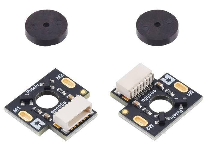
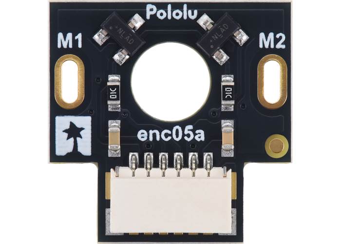
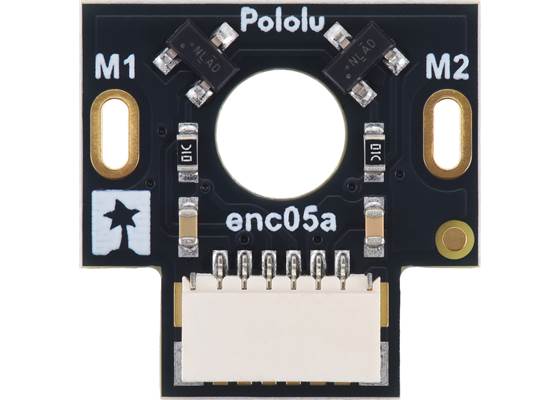
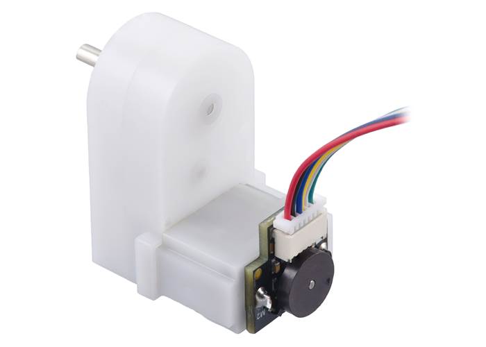
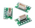
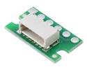
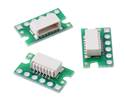
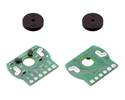
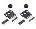
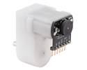
Add quadrature encoders to your mini plastic gearmotors with this kit that uses a magnetic disc and Hall effect sensors to provide 12 counts per revolution of the motor shaft.
Special Order
Shipping from $4.90
+10 more from our supplier in 7-10 days
Our Code: SKU-011458
Supplier Link: [Pololu MPN:3547]
Add quadrature encoders to your mini plastic gearmotors with this kit that uses a magnetic disc and Hall effect sensors to provide 12 counts per revolution of the motor shaft. The sensors operate from 2.7 V to 18 V and provide digital outputs that can be connected directly to a microcontroller or other digital circuit. These encoders have a side-entry, 6-pin male JST SH-type connector, and we have compatible cables available in a variety of lengths.
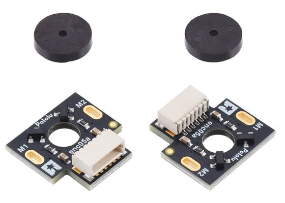
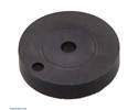
This kit includes two encoder boards and two magnetic discs.
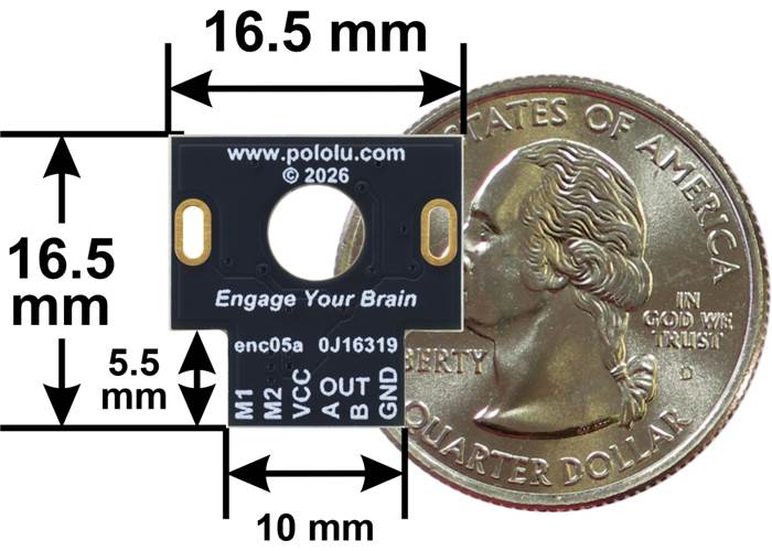
This kit includes two dual-channel Hall effect sensor boards and two 6-pole magnetic discs that can be used to add quadrature encoding to two mini plastic gearmotors (motors and cables are not included with this kit). The encoder board senses the rotation of the magnetic disc and provides a resolution of 12 counts per revolution of the motor shaft when counting both edges of both channels. To compute the counts per revolution of the gearbox output shaft, multiply the gear ratio by 12. This compact encoder solution fits within the 11.5 mm × 22.5 mm cross section of the motors on three of the four sides, and it extends approximately 5.5 mm past the edge of the quarter side.

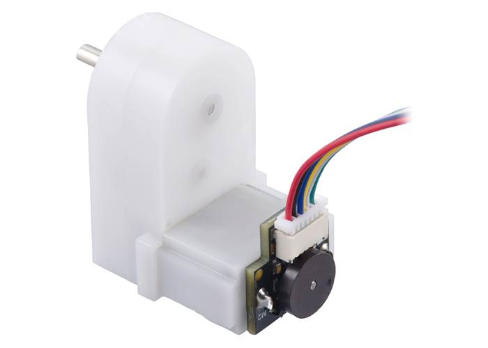
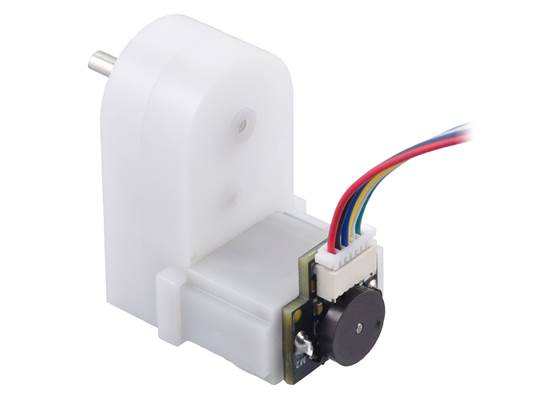
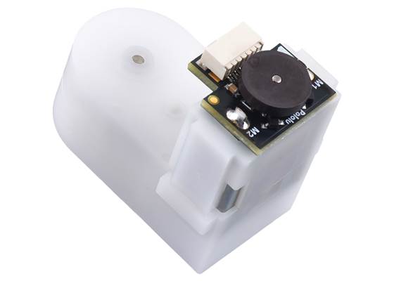
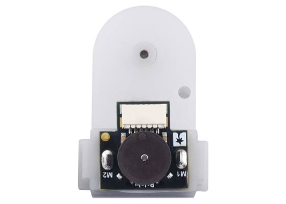
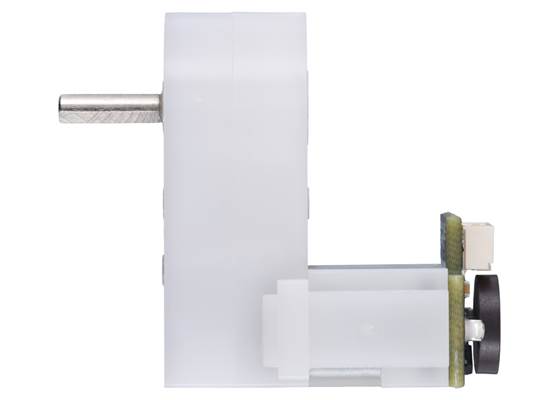
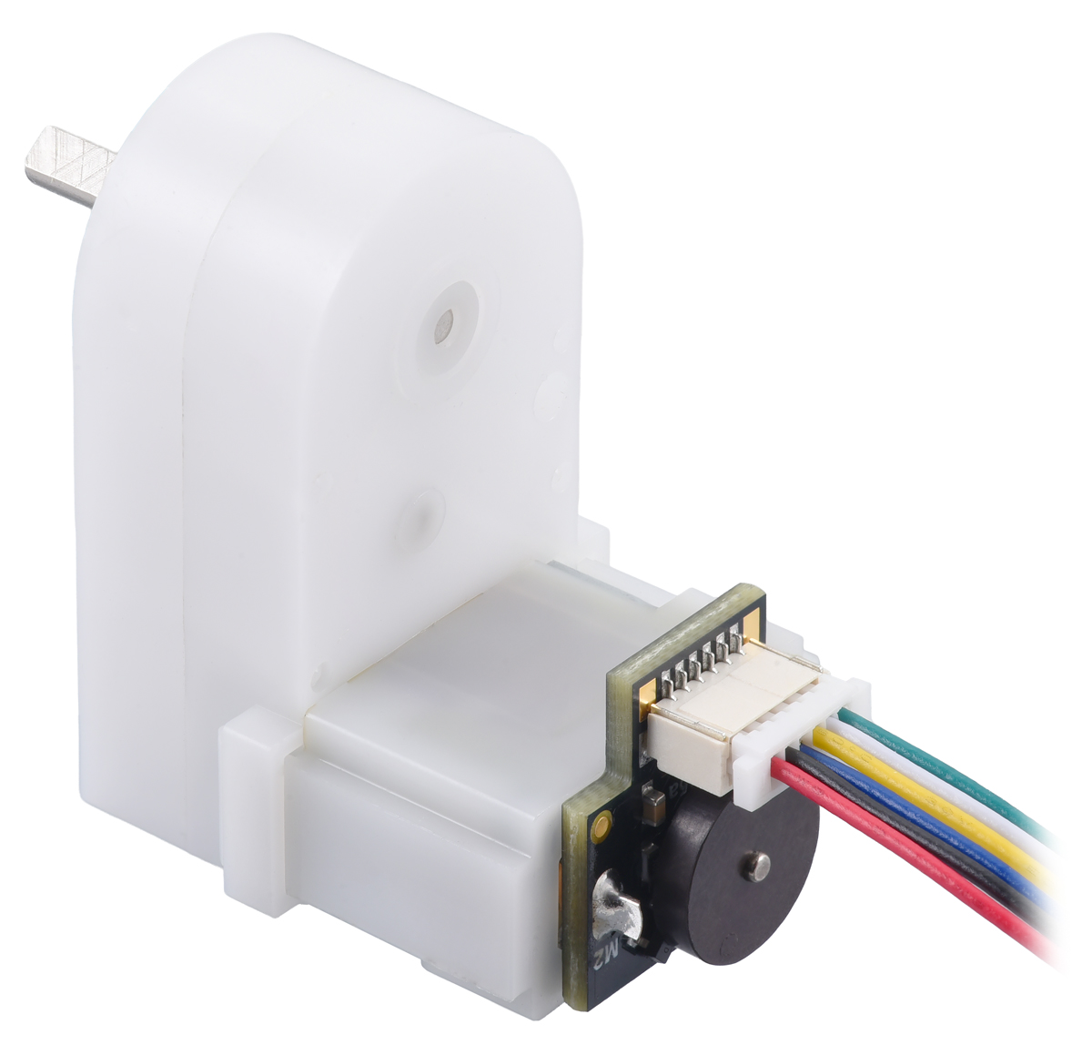
Magnetic Encoder with Side-Entry Connector on a Mini Plastic Gearmotor.

Magnetic Encoder with Side-Entry Connector on a Mini Plastic Gearmotor. (1)

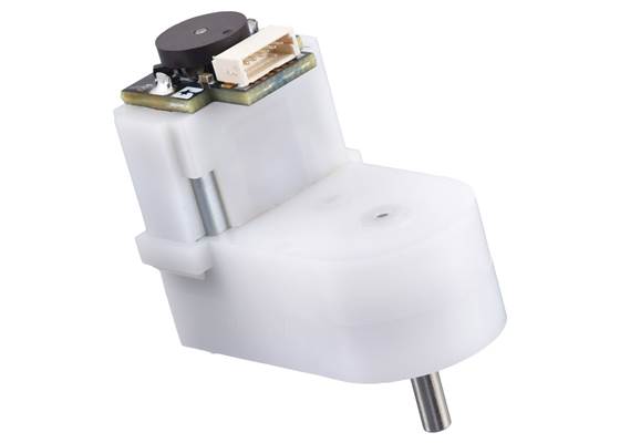
Magnetic Encoder with Side-Entry Connector on a Mini Plastic Gearmotor. (2) (2)

Magnetic Encoder with Side-Entry Connector on a Mini Plastic Gearmotor. (3) (3)
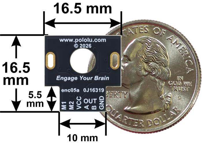
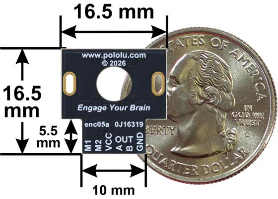
Basic dimensions of the Magnetic Encoder with JST SH-Type Connector (Top-Entry or Side-Entry) for Mini Plastic Gearmotor.
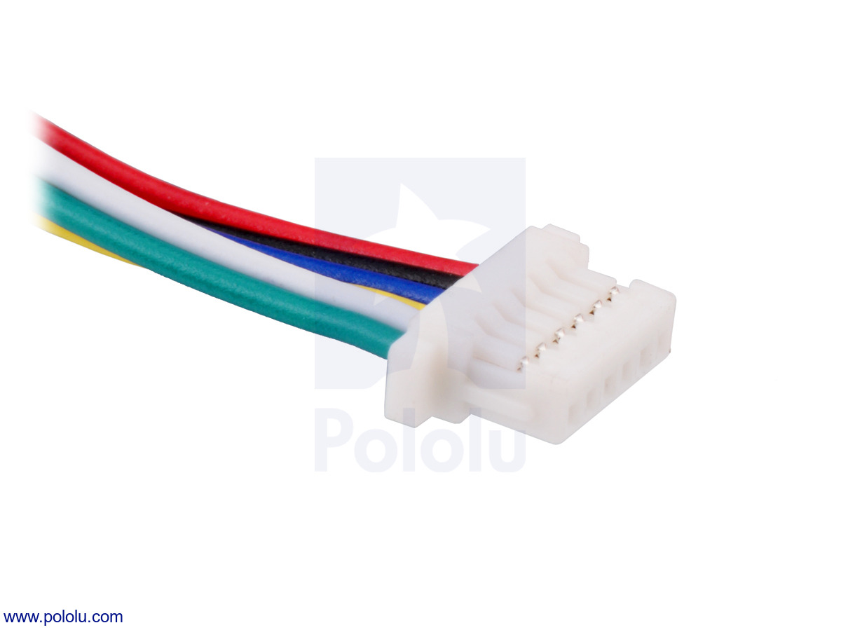
The encoders include a side-entry, 6-pin male JST SH-type connector with a 1mm pitch that is compatible with our 6-pin JST SH-type cables. We also carry a version of this encoder with a top-entry connector; the following pictures show a comparison of the side-entry (left) and top-entry (right) versions:
Magnetic Encoder with Side-Entry Connector on a Mini Plastic Gearmotor (cable not included). |
|
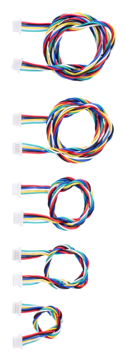
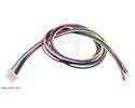
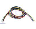
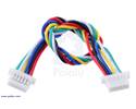
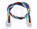
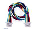
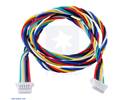
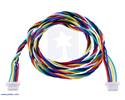
We have two types of cables with matching JST SH-style connectors that can be used with these encoders. Single-ended versions have a connector on one end and unterminated wires on the other, while double-ended cables have twisted wires with female connectors on both ends.
Single-ended cables:
| • 75 cm (30″) • 30 cm (12″) • 12 cm (4.5″) |
|
Double-ended cables:
| • 63 cm (25″) • 40 cm (26″) • 25 cm (10″) • 16 cm (6.3″) • 10 cm (4″) |
|
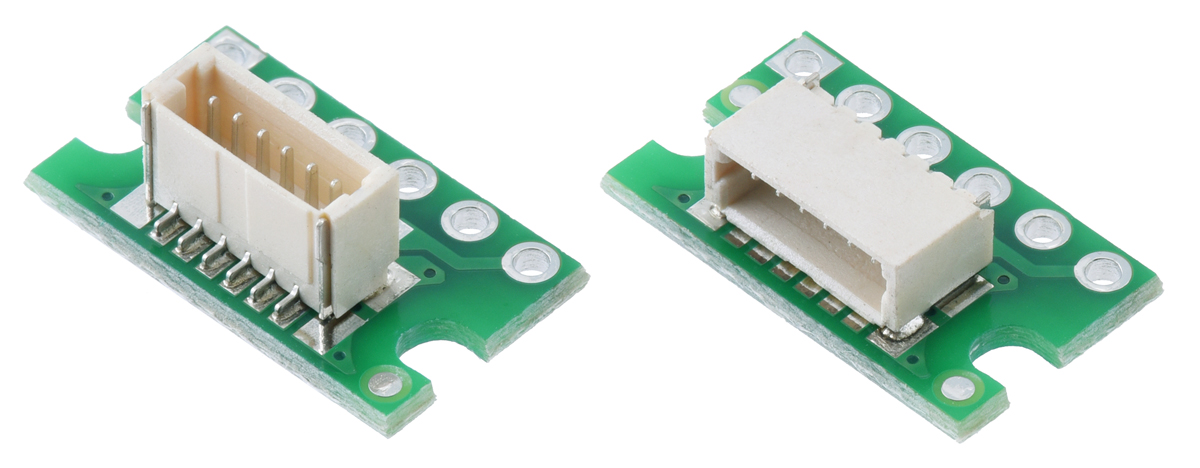
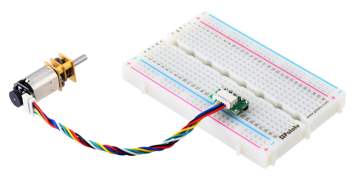
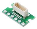
The double-ended cables can be used with our JST SH-style connector breakout boards (available in top-entry and side-entry versions) to easily access the motor and encoder pins on a standard solderless breadboard. The right picture below shows an example of this with our similar micro metal gearmotor encoder.
|
|
|
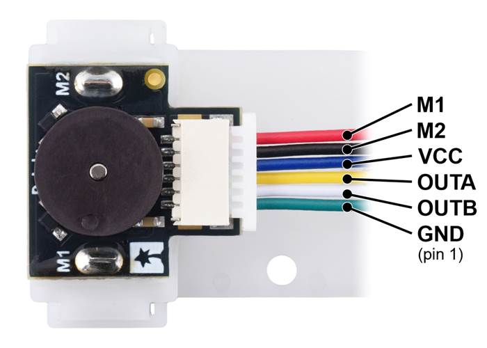
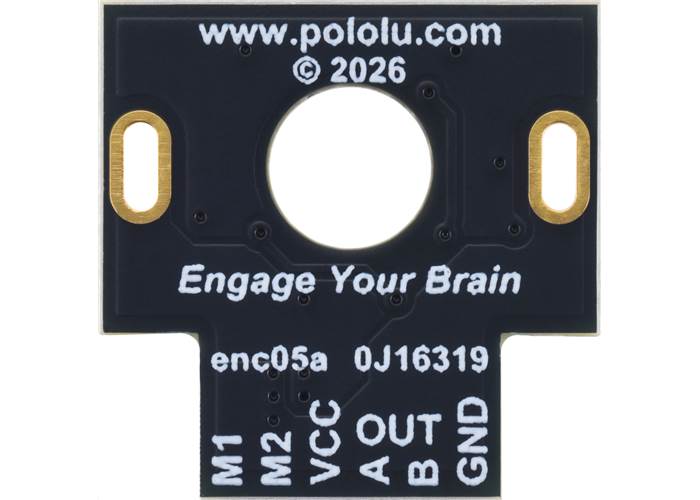
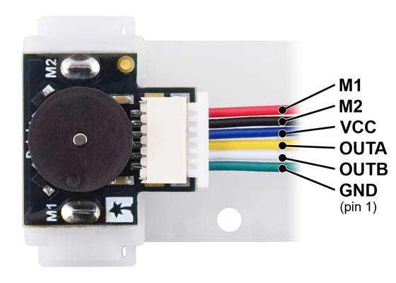
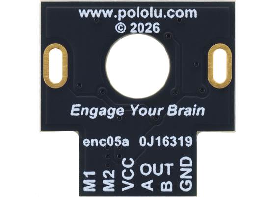
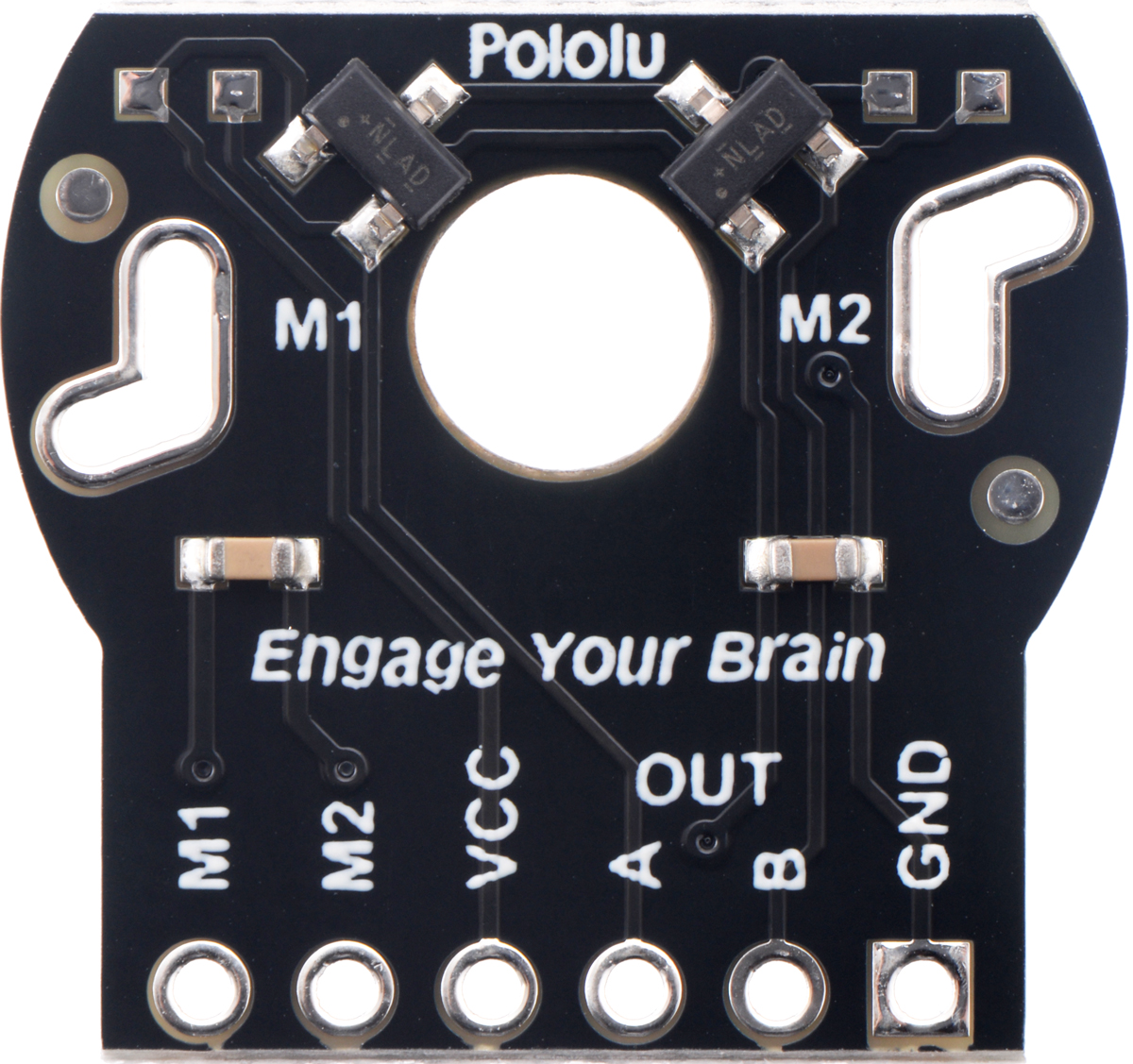
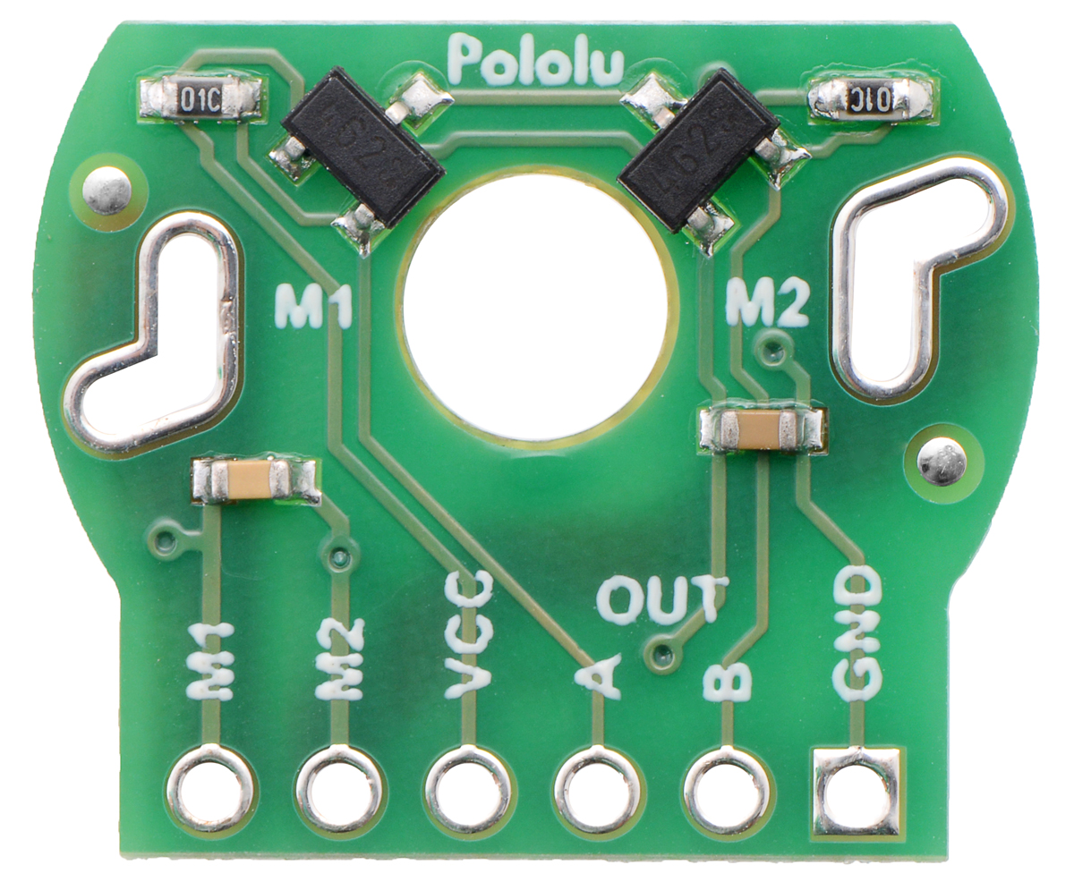
The encoder board is designed to be soldered directly to the back of the motor, with the back shaft of the motor protruding through the hole in the middle of the circuit board. One way to achieve good alignment between the board and the motor is to tack down the board to one motor pin and to solder the other pin only when the board is flat and well aligned. Be careful to avoid prolonged heating of the motor pins, which could deform the plastic motor case or the motor brushes. Once the board is soldered down to the two terminals, the motor leads are connected to the M1 and M2 connector pins as labelled below, and they can be accessed via the red and black wires when used with our corresponding JST cables. The remaining four connector pins are used to power the sensors and access the two quadrature outputs:
| Pin | Wire colour | Function |
|---|---|---|
| 1 | Green | encoder GND |
| 2 | White | encoder channel B output |
| 3 | Yellow | encoder channel A output |
| 4 | Blue | encoder Vcc (2.7 V to 18 V) |
| 5 | Black | motor power M2 |
| 6 | Red | motor power M1 |
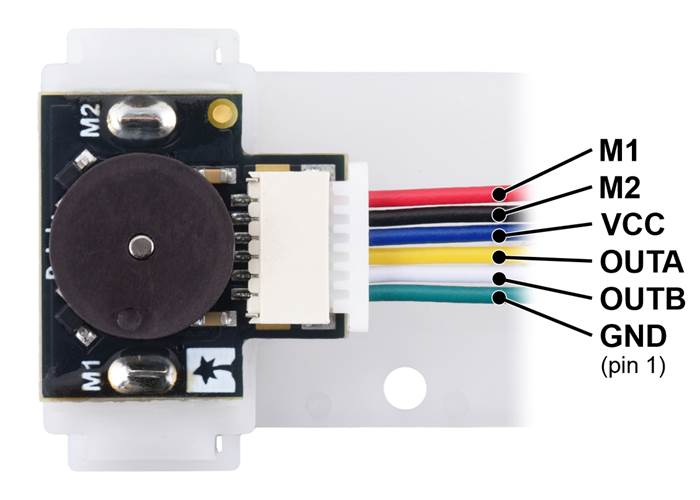
Pinout of the Magnetic Encoder with Side-Entry Connector for Mini Plastic Gearmotor (cable not included).
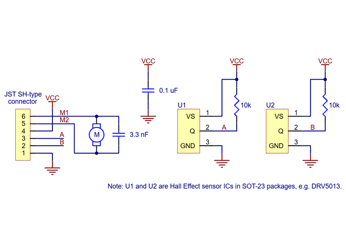
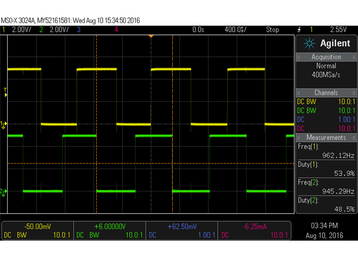
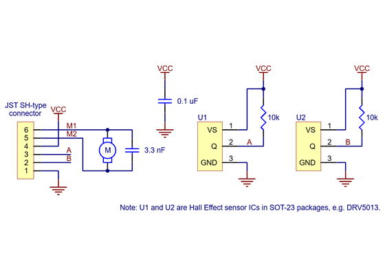
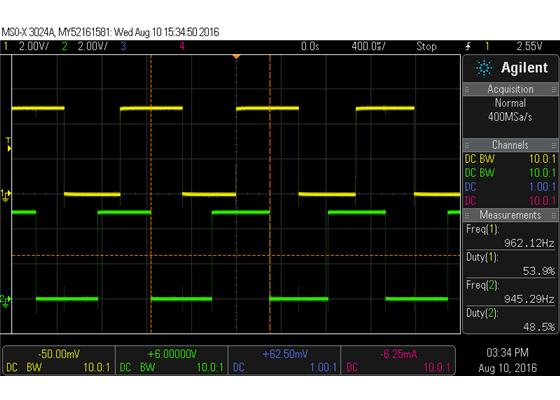
The sensors are powered through the VCC (blue wire) and GND (green wire) pins. VCC can be 2.7 V to 18 V, and the quadrature outputs A and B (yellow and white wires) are digital signals that are either driven low (0 V) by the sensors or pulled to VCC through 10 kΩ pull-up resistors, depending on the applied magnetic field. The sensors’ comparators have built-in hysteresis, which prevents spurious signals in cases where the motor stops near a transition point.
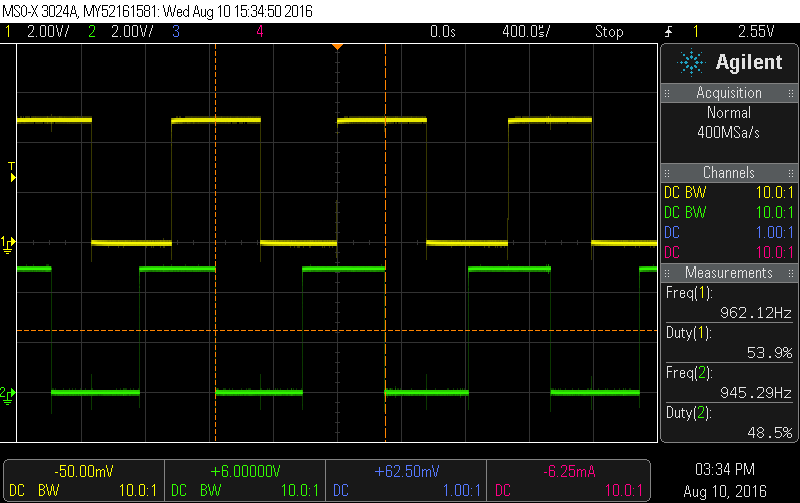 |
Encoder A and B outputs of a magnetic encoder on a high-power (HP) mini plastic gearmotor running at 4.5 V. |
|---|
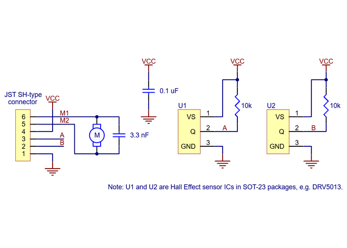
Schematic diagram of the Magnetic Encoder with JST SH-Type Connector (Top-Entry or Side-Entry) for Mini Plastic Gearmotor.
This encoder module improves on our previous encoder boards for mini plastic gearmotors by adding a connector to enable the use of removable cables. The basic schematic is unchanged, and the electrical performance is identical aside for the lower minimum operating voltage. The following pictures show the two newer encoders with JST SH-type connectors next to the original ones:
|
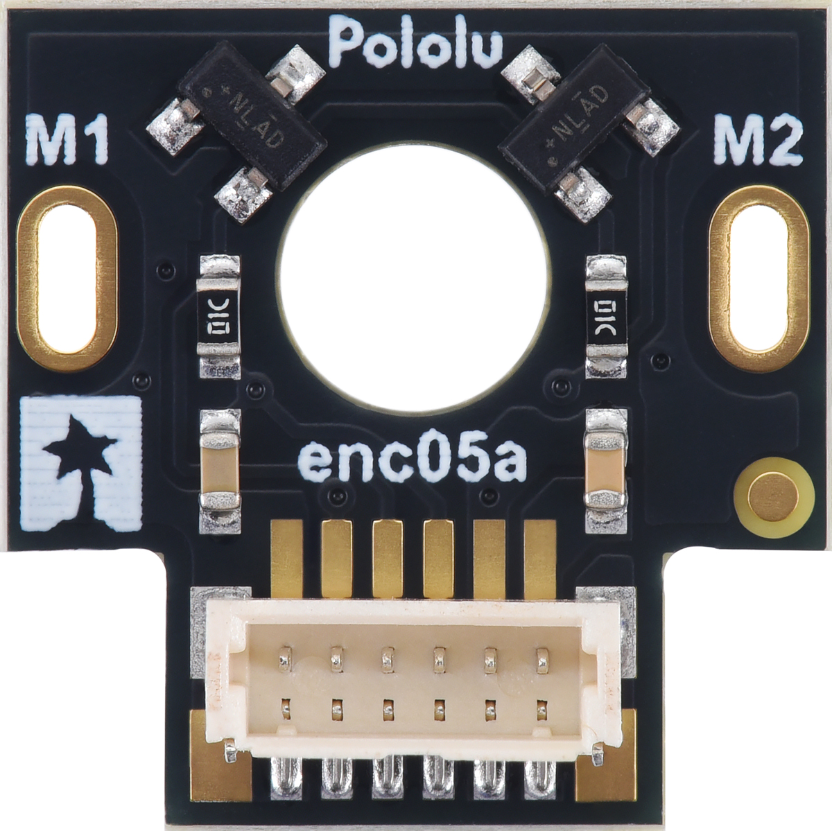
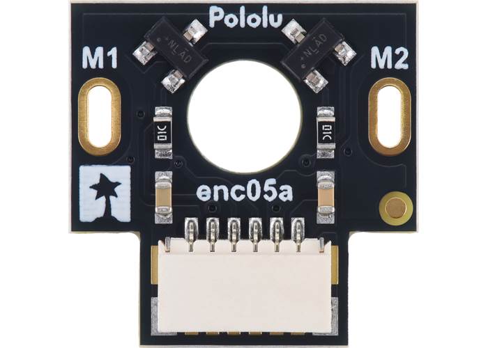
Magnet-side view of the Magnetic Encoder with Side-Entry Connector for Mini Plastic Gearmotor, 12 CPR, 2.7-18V. |
|
|
| Size: | 16.5 mm × 16.5 mm |
|---|---|
| Weight: | 3 g1 |
| Minimum operating voltage: | 2.7 V |
|---|---|
| Maximum operating voltage: | 18 V |
| Connector: | side-entry, 6-pin male, JST SH-type |
| PCB dev codes: | enc05a |
|---|---|
| Other PCB markings: | 0J16319 |
This file contains dimension diagrams for the Magnetic Encoder Pair Kit with Top-Entry Connector and the Magnetic Encoder Pair Kit with Side-Entry Connector.
This file contains 3D models (in the step file format) of the components for the Magnetic Encoder Pair Kit with Top-Entry Connector and the Magnetic Encoder Pair Kit with Side-Entry Connector.
This DXF drawing shows the locations of all of the board’s holes.

 Brands