"The little board that can"
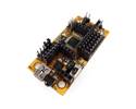
The DAGU S4A EDU (also known as the Mini-Driver MkII) control board is an Arduino based miniature control board with a number of add-ons making it ideal for embedded projects, Beginners and Educators. It can also use the Scratch Programming Language that has been designed especially for education and schools. Use the S4A scratch variant with this board.
The controller includes an ATMEGA328P (5V @ 16Mhz) with Arduino boot loader, Dual Channel DC motor controller (up to 2.5Amps per channel) and can drive up to 8 Servos.
Some additional features are also in place including Battery Level monitoring, a wide range of power input (5-9V) and a master On-Off switch for your project.
This controller offers a lower cost, feature rich solution for small and embedded projects.
Features
- ATMEGA328P 5V @ 16Mhz, 32K Flash, 2K SRAM, 1K EEPROM with Arduino boot loader
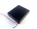
- Power supply voltage: 6-9V
- Dual Channel DC Motor Driver up to 2A per channel.
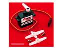
- Supports up to 8 Servos.
- Battery Level monitoring available on pin A7
- A6 is accessible through a solder pad in the back if needed.
- Built in LED connected to D13.
- Pins for up to 8 servos.
- Expansion port for use with a Bluetooth or Xbee module
- CP2102 USB serial interface with Mini-B USB socket and 500mA PTC fuse.
- Built in power Switch and Reset button.
- Digital pins on servo compatible 3 pin headers with selectable voltage (+Battery or +5V).
- Analog pins on servo compatible 3 pin headers with +5V and Gnd to power sensors.
- D13 LED.
- ISP header.
- Compatible with the DAGU Bluetooth Module (available separately)"
Downloads
Dagu Mini Driver Manual (pin out details and specs)
Dagu Mini Driver Manual (older version but more details on using the device)
Using The Arduino Software
Download and install the Arduino Software from the official Arduino site.
Download and install the device drivers from the Silicon Labs website. These allow your computer to talk to the board over USB.
Start the Arduino Software.
- From the menu select,
- File-> Examples -> 01.Basic -> Blink
- Tools-> Serial Port -> COM3 (the number will vary but there should be one if your board is connected)
- Tools-> Board -> Arduino Nano, ATMega328P
- Tools-> Programmer->AVRISP mkII
- Then upload the sketch, File->Upload
Operation
FAQ:
- My board is not recognized by my computer or the COMM ort does not show up in the Arduino IDE
You need to install the CP2102 USB drivers first. These can be downloaded from the Silicon Labs website.
Disconnect the Arduino board, install the drivers (and reboot if required). Re connect the board.
After re-connecting the board a new COM port should be visible in Device Manager and the Arduino IDE. You may need to restart the Arduino IDE to recognize the new port.
- I can't load the program onto my board - or- I'm getting
stk500: Not in sync errors
In the Arduino IDE, go to the Board Menu, and select " Arduino Nano, ATMega328P".
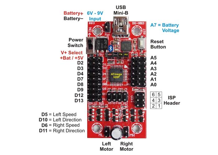
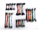
- How to drive the DC Motors
To drive the DC motors make sure the jumpers are correctly inserted in pins D7-D10. The pins control the Direction and Speed of each motor:
- D5 is left motor speed
- D10 is left motor direction
- D6 is right motor speed
- D11 is right motor direction
To make a motor move, first set the direction by doing a digitalWrite of HIGH or LOW (for Forward/Reverse) to the direction pin. Next set the motor speed by doing an analogWrite of 0~255 to the speed pin. 0 is stopped and 255 is full throttle.
- How to use Servos
Up to 8 Servos can be connected to Digital pins D2-D6 and D11-D13. You must set the "+V" jumper (located under the power switch) to Vbat in order to power the servos. Each servo must be connected so that the Black wire connects to the GND pin.
For programming information, please refer to the Arduino Servo library here https://www.arduino.cc//en/Reference/Servo
- How to turn the LED on and Off
The LED is connected to Digital Pin 13. To use it perform a digitalWrite(13, HIGH) to turn it on or digitalWrite(13, LOW) to turn it off.
For more information and an example see the Arduino documentation here https://www.arduino.cc//en/Reference/digitalWrite
- How to read the Battery level
The battery level can be monitored by reading Analog pin A7. In the code, simply perform an analogRead(7).
A reading of 512 corresponds to approximately 5V. To prevent damage to the boot loader and the board, you must stop using it once the battery level drops to 5V.
- How to Install and use the optional DAGU Bluetooth Module
The Board is compatible with the DAGU Bluetooth Module. The module is inserted on the board respecting the position of the Vcc and Gnd pins.
The BT board connects to the default RX and TX pins of the Arduino (Digital pins 0 and 1). You can use the Arduino Serial library to send and receive data over Bluetooth.
By default the Bluetooth module comes Pre programmed for 9600bps 8N1 but please refer to the module's documentation for additional information.