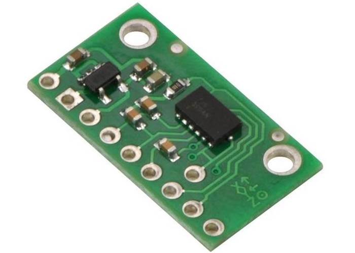
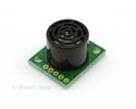
This triple-axis accelerometer is a carrier board for the Freescale MMA7361L XYZ-axis accelerometer, a great low-g sensor with analog voltage outputs and adjustable sensitivity (±1.5 g or ±6 g), and a 0g-detect digital output that signals when the board is in free-fall. The board has a 3.3V linear regulator that enables an input voltage range of 2.2-16 V.
On Sale!
Was $15.95
In stock in Australia
Shipping from $4.90
Our Code: SEN-10029
Supplier Link: [Pololu MPN:1251]
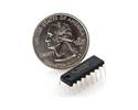
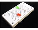
This three-axis accelerometer is a breakout board for Freescale’s MMA7361L (175k pdf) MEMS (micro-electro-mechanical systems) low-g accelerometers; we therefore recommend careful reading the appropriate datasheet for your particular carrier board before using this product. The MMA7361 are great ICs, but their small, leadless packages makes them difficult for the typical student or hobbyist to use. This carrier board includes all of the components in the part’s recommended connection diagram and includes a 3.3V 50mA ultra-low-dropout linear voltage regulator, which allows the accelerometer breakout board to accept a wide range of input voltages (2.2-16 V) with power to spare for additional 3.3V components. The accelerometer’s pins are 0.1" spaced to work well with standard solderless breadboards and 0.1" perfboards.
The boards offer selectable ±1.5g or ±6g sensitivities with a 0g-detect output that goes high when the board is in free fall.

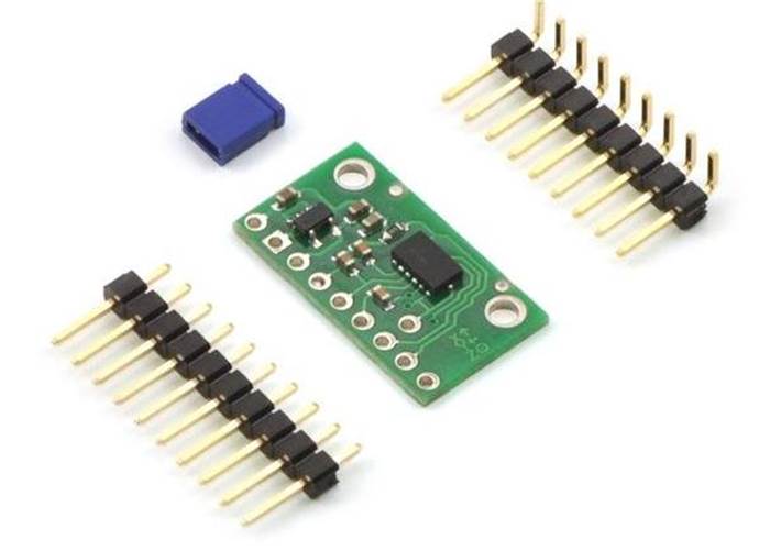
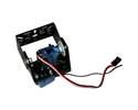
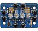
A 10×1 strip of 0.1" header pins, a 9×1 strip of 0.1" right-angle header pins and one shorting block are included, as shown in the picture to the right.
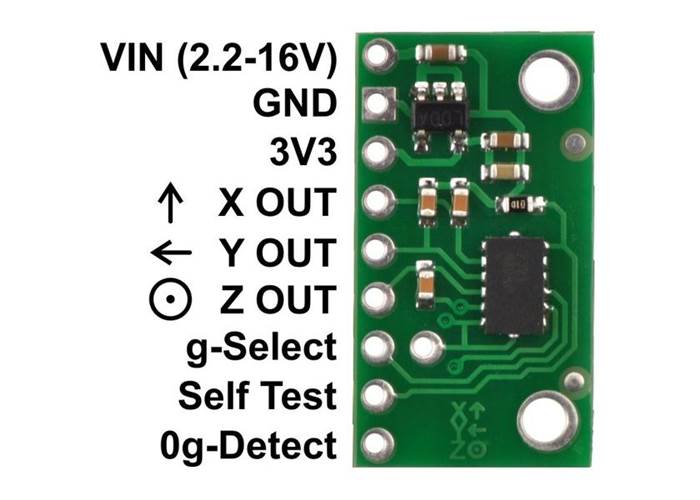
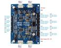
 To power the three-axis accelerometer, connect 2.2-16 V battery or power supply to the VIN pin. Note that this part does not have 5V-tolerant pins, so external components (such as voltage dividers) are required when interfacing the board’s g-Select and Self Test pins with 5V systems. Connections to the g-Select and Self Test pins are optional; the board will work with these pins disconnected.
The accelerometer X, Y, and Z outputs are three separate analog voltages centered at half the voltage of the 3V3 pin. Positive accelerations along an axis increase that axis’s output voltage above the center voltage and negative accelerations decrease the output voltage below the center voltage. The outputs will always be within the range of 0 to the voltage of the 3V3 pin.
The sensitivity selection pin, g-Select, is internally pulled low, which selects for a default sensitivity of ±1.5g (800 mV/g) on the MMA7361L carrier. Driving the pin high selects for a sensitivity of ±6g (206 mV/g) on the MMA7361L carrier.
The 0g-Detect pin outputs high when all three axes simultaneously detect 0g, which happens when the board is in free-fall. This pin is only documented in the datasheet of the more sensitive MMA7361L IC .
The Self Test pin is pulled low on the board and can be left disconnected.
For very low power applications, the three-axis accelerometer can be powered by a 2.2-3.6V IO pin connected to 3V3. This lets you bypass the regulator avoiding its small current draw and allows the microcontroller to control power to the board and turn it off when not in use.
File downloads