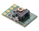
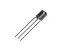
The QTR-L-1A reflectance sensor incorporates a right-angle infrared LED and a right-angle phototransistor in an inexpensive, tiny 0.35″ × 0.3″ module that can be mounted almost anywhere and is great for edge detection and line following.
Special Order
Shipping from $9.90
+263 more from our supplier in 7-10 days
Our Code: SKU-003239
Supplier Link: [Pololu MPN:2454]
The QTR-L-1A reflectance sensor incorporates a right-angle infrared LED and a right-angle phototransistor in an inexpensive, tiny 0.35″ × 0.3″ module that can be mounted almost anywhere and is great for edge detection and line following. The reflectance measurement is output as an analog voltage. This sensor is sold in packs of two units.
Note: The QTR-L-1A reflectance sensor requires an analogue input to take readings. The similar QTR-L-1RC reflectance sensor is available with a digital I/O-compatible output.
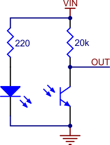 |
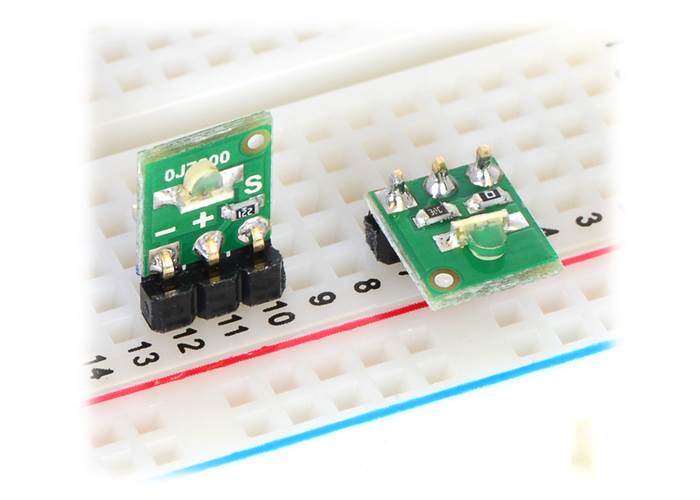
The Pololu QTR-L-1A reflectance sensor carries a right-angle infrared LED and a right-angle phototransistor, both pointing towards the front edge of the board. The phototransistor is connected to a pull-up resistor to form a voltage divider that produces an analogue voltage output between 0 V and VIN (which is typically 5 V) as a function of the reflected IR. Lower output voltage is an indication of greater reflection.
The LED current-limiting resistor is set to deliver approximately 17 mA to the LED when VIN is 5 V. The current requirement can be met by some microcontroller I/O lines, allowing the sensor to be powered up and down through an I/O line to conserve power.
This sensor was designed to be used with the board perpendicular to the surface being sensed, and narrow-angle lenses built into the infrared LED and phototransistor packages allow it to be effective to a range of about 1″ (25 mm). Because of its small size, multiple units can easily be arranged to fit various applications such as line sensing and proximity/edge detection. The QTR-L-1A is sold in packs of two units.
For a similar sensor that can be used with the board parallel to the surface, but with shorter range, please see the QTR-1A reflectance sensor. We also offer arrays of three and eight sensors: the QTR-3A reflectance sensor array and the QTR-8A reflectance sensor array.
 |
QTR sensor size comparison. Top row: QTRX-HD-07, QTR-HD-07; middle row: QTR-3, QTR-1, QTR-L-1; bottom row: QTR-8. |
|---|

QTR-L-1A reflectance sensor emitter and detector sides with labeled pinout.
There are several ways you can interface with the QTR-L-1A output:
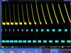
This last method will work if you are able to get high reflectance from your white surface (so that there is a large output voltage difference over black and white surfaces), but will probably fail if you have a lower-reflectance signal profile. The following table shows some typical output voltages from the sensor over different surfaces and at different distances:
| White surface | 3/4″ black electrical tape | |
|---|---|---|
| 0.25″ distance | 0.2 V | 3.8 V |
| 1″ distance | 2.4 V | 3.5 V |
Ambient light, especially sunlight, can affect the sensor readings significantly. If the output voltage from the QTR-L-1A is consistently low, you might need to add shielding around the sensor or mount it in a different location to reduce interference from outside light sources.
Our Pololu AVR library provides functions that make it easy to use these sensors with our Orangutan robot controllers; please see the QTR Reflectance Sensors section of our library command reference for more information. We also have a Arduino library for these sensors.
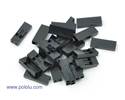
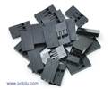
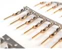
Each pack of two reflectance sensors includes sets of straight male header strips and right-angle male header strips, which allow you to mount them in the orientation of your choice. You can also solder wires, such as ribbon cable, directly to the pads for the most compact installation.
QTR-L-1A or QTR-L-1RC reflectance sensor (2-pack) with included header pins. |
QTR-L-1A and QTR-L-1RC reflectance sensors plugged into a breadboard in two possible orientations. |
| Other PCB markings: | 0J7200 |
|---|
Information about using the Pololu QTR reflectance sensors, including differences between A-type and RC-type sensors and sample oscilloscope screen captures of sensor outputs.
Information about installing and using the C/C++ libraries provided for use with Pololu products.

A reference to commands provided in the Pololu C/C++ and Arduino libraries for the AVR.
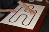
Step-by-step instructions for building your own line-following courses.
This DXF drawing shows the locations of all of the board’s holes.
Un guide utiliser et exploiter un senseur QTR (détecteur de ligne) (version 0.1). Note: This French translation of our QTR sensor documentation was made by our distributor MCHobby.
Matthew Phillipps ported our Arduino Library for the Pololu QTR Reflectance Sensors to the mbed platform. The Arduino library is designed to work with Pololu QTR reflectance sensors, so the mbed library should too, but Matthew points out he only tested it with the analogue sensors. This library was not written and is not maintained by Pololu.
This library for Arduino makes it easy to interface with Pololu QTR Reflectance Sensors.