This shield makes it easy to control two brushed DC motors with your Arduino or Arduino-compatible board. Its dual TB9051FTG motor drivers operate from 4.5 to 28 V and can deliver a continuous 2.6 A per motor (5 A peak).
Special Order
Shipping from $4.90
+235 more from our supplier in 7-10 days
Our Code: SKU-004769
Supplier Link: [Pololu MPN:2520]
This shield makes it easy to control two brushed DC motors with your Arduino or Arduino-compatible board. Its dual TB9051FTG motor drivers operate from 4.5 to 28 V and can deliver a continuous 2.6 A per motor (5 A peak). These great drivers also offer current-sense feedback and accept ultrasonic PWM frequencies for quieter operation. A fixed current chopping threshold allows each TB9051 to limit the peak motor current, and they feature built-in protection against under-voltage, over-current, and over-temperature conditions; our shield also adds reverse-voltage protection. The Arduino pin mappings can all be customized if the defaults are not convenient, and the motor driver control lines are broken out along the left side of the shield for general-purpose use without an Arduino.
This motor driver shield and its corresponding Arduino library make it easy to control two bidirectional, brushed DC motors with an Arduino or compatible board, such as the A-Star 32U4 Prime. The board features a pair of Toshiba TB9051FTG motor drivers, which operate from 4.5 to 28 V and can deliver up to 2.6 A per channel continuously, and includes current sense circuitry, reverse battery protection, and logic gates to reduce the required number of I/O pins. The drivers automatically limit the peak current to around 5 A, which they can deliver for a few seconds in typical applications before the thermal protection activates.
This versatile motor driver is intended for a wide range of users, from beginners who just want a plug-and-play motor control solution for their Arduinos (and are okay with a little soldering) to more advanced users who want a general-purpose dual-channel version of our single-channel TB9051FTG carrier to use with other microcontroller boards, outside of the Arduino environment. The Arduino pin mappings can all be customised if the defaults are not convenient, and the simplified TB9051FTG control lines are broken out along the left side of the board, providing a convenient interface point for other microcontroller boards. This versatility, along with an option to power the Arduino from the shield, either directly or through an added regulator, sets this board apart from similar competing motor shields.
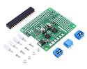
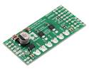
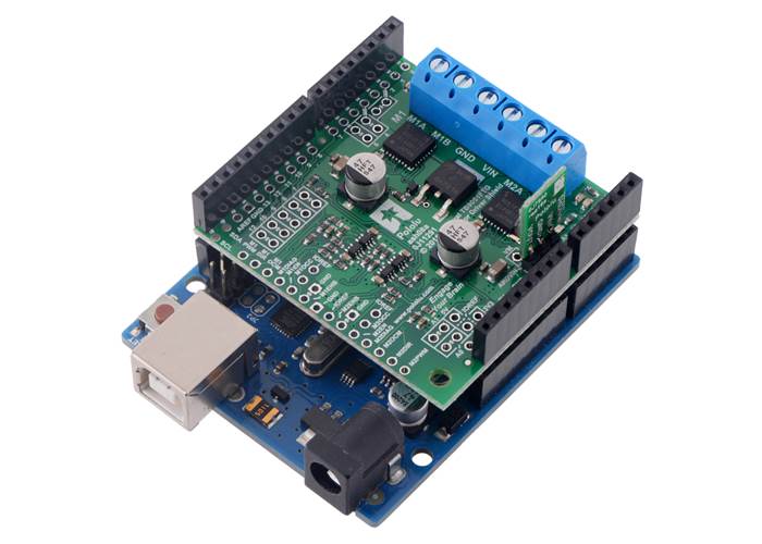
Dual TB9051FTG Motor Driver Shield for Arduino. (1) |
Dual TB9051FTG Motor Driver Shield for Arduino, bottom view. |
The board ships fully populated with its SMD components, including the two TB9051 ICs, as shown in the left picture above; stackable Arduino headers and terminal blocks for connecting motors and motor power are included but are not soldered in (see the Included hardware section below).
For a higher-power alternative to this shield, please consider the dual VNH5019 motor driver shield, which can deliver a continuous 12 A per channel, and for lower-power, lower-cost alternatives, consider the dual MAX14870 motor driver shield, DRV8835 dual motor driver shield, or A4990 dual motor driver shield. We also have a similar dual TB9051FTG motor driver intended specifically for use with the Raspberry Pi.
Dual TB9051FTG Motor Driver Shield on an Arduino Uno (with a regulator added to power the Arduino from the shield’s VIN).

Dual TB9051FTG Motor Driver Shield for Arduino, bottom view with dimensions.
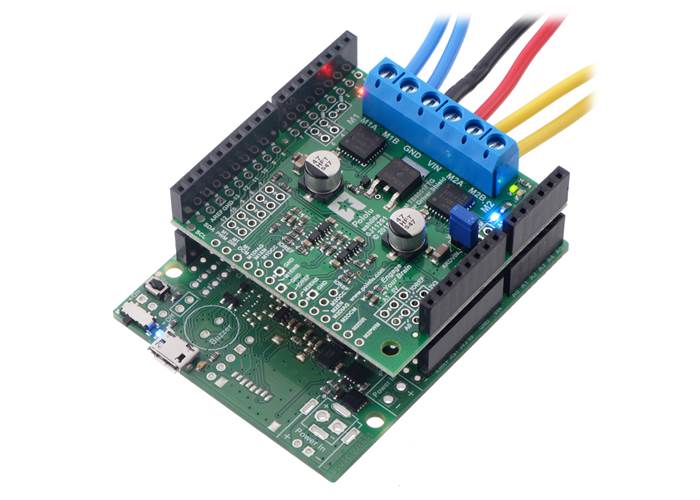
Dual TB9051FTG Motor Driver Shield for Arduino being controlled by an A-Star 32U4 Prime SV.
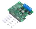
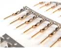
This motor driver board ships with all of the surface-mount parts populated. However, soldering is required for assembly of the included through-hole parts. The following through-hole parts are included:
A 0.1″ shorting block (for optionally supplying shield power to Arduino) is also included.

Dual TB9051FTG Motor Driver Shield for Arduino with included hardware.
The terminal blocks can be soldered into the larger holes to allow for convenient temporary connections of unterminated power and motor wires (see our short video on terminal block installation), or you can break off a 12×1 section of the 0.1″ header strip and solder it into the smaller through-holes that border these larger holes. You can also solder wires directly to the board.
When not using this board as an Arduino shield, you can solder the pieces of the 0.1″ header to the logic connections along the left side of the board to enable use with custom cables or solderless breadboards, or you can solder wires directly to the board for more compact installations. Note that motor and motor power connections should not be made through a breadboard.

Schematic diagram of the Dual TB9051FTG Motor Driver Shield for Arduino.
This diagram is also available as a downloadable pdf: Dual TB9051FTG Motor Driver Shield for Arduino schematic (299k pdf).
The current monitor outputs, M1OCM and M2OCM, provide an analogue current-sense feedback voltage of approximately 500 mV per A. By default, these outputs are connected to Arduino analogue inputs A0 and A1, respectively. Note that each of these outputs is only active while the corresponding H-bridge is driving; it is inactive (low) when the driver is braking or the motor outputs are high impedance (floating). If the driver is braking, current will continue to circulate through the motor, but the voltage on the OCM pin will not accurately reflect the motor current. Please note that like most motor drivers with integrated current sense, the actual sensitivity can vary significantly from unit to unit, and accuracy can be especially poor at low currents (see the TB9051FTG datasheet (2MB pdf) for more information). Please consider our Hall effect current sensors as options for adding more consistent and accurate current sensing to your system.
The TB9051FTG will start chopping its output current at a typical threshold of 6.5 A. However, the chip by itself will typically overheat at lower currents. In our tests, we found that the chip was able to deliver 5 A for only a few seconds before the chip’s thermal protection kicked in; a continuous current of about 2.6 A per channel was sustainable for many minutes without triggering thermal current limiting or an over-temperature shutdown. The actual current you can deliver will depend on how well you can keep the motor driver cool. The shield’s printed circuit board is designed to help with this by drawing heat out of the motor driver chip. PWMing the motor will introduce additional heating proportional to the frequency.
Unlike typical H-Bridges, the TB9051FTG has a feature that allows it to gracefully reduce the maximum current limit when the chip temperature approaches its limit. This means that if you push the chip close to its limit, you will see less power to the motor, but it might allow you to avoid a complete shutdown.
This product can get hot enough to burn you long before the chip overheats. Take care when handling this product and other components connected to it.
| Size: | 1.90″ × 2.02″ × 0.3″1 |
|---|---|
| Weight: | 11 g1 |
| Motor driver: | TB9051FTG |
|---|---|
| Motor channels: | 2 |
| Minimum operating voltage: | 4.5 V2 |
| Maximum operating voltage: | 28 V3 |
| Continuous output current per channel: | 2.6 A4 |
| Peak output current per channel: | 5 A |
| Current sense: | 0.5 V/A |
| Maximum PWM frequency: | 20 kHz |
| Reverse voltage protection?: | Y5 |
| PCB dev codes: | ash08a |
|---|---|
| Other PCB markings: | 0J11291 |
User’s manual for the Pololu Dual TB9051FTG Motor Driver Shield for Arduino.
This DXF drawing shows the locations of all of the board’s holes.
This library for the Arduino makes it easy to interface with Pololu’s Dual TB9051FTG Motor Driver Shield and drive a pair of brushed DC motors. A sample sketch is included with the library.
Toshiba’s product page for the TB9051FTG brushed motor driver IC, with links to its most up-to-date datasheet in several languages and other resources.