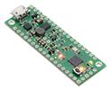
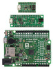
The A-Star 32U4 Mini SV is a programmable module based on the ATmega32U4 from Microchip (formerly Atmel). Unlike competing products, it has an on-board switching step-down regulator that allows it to be powered efficiently from a 5 V to 40 V supply.
Special Order
Shipping from $4.90
+266 more from our supplier in 7-10 days
Our Code: SKU-004655
Supplier Link: [Pololu MPN:3145]
The A-Star 32U4 Mini SV is a programmable module based on the ATmega32U4 from Microchip (formerly Atmel). Unlike competing products, it has an on-board switching step-down regulator that allows it to be powered efficiently from a 5 V to 40 V supply. This compact 1.9″ × 0.7″ board breaks out all 26 of the microcontroller’s I/O pins (of which 7 can be used as PWM outputs and 12 as analog inputs), and loading programs is made easier by a Micro-USB interface and a preloaded Arduino-compatible bootloader.
The Pololu A-Star 32U4 Mini boards are general-purpose programmable modules based on the ATmega32U4 AVR microcontroller from Microchip (formerly Atmel), which has 32 KB of flash program memory, 2.5 KB of RAM, and built-in USB functionality. The A-Star (abbreviated A*) adds a number of onboard features to support the microcontroller and make it easier to work with, including a 16 MHz crystal, a USB Micro-B connector, an in-system programming (ISP) header, a reset button, and three indicator LEDs.

A-Star 32U4 Mini ULV, LV, and SV.
Each A-Star 32U4 Mini contains a switching regulator that efficiently produces 5 V from an external voltage source to power the microcontroller. Three different versions are available, covering a wide range of input voltages:
A robust power selection circuit enables seamless transitions between regulator power and USB power, and overcurrent and reverse-voltage protection help safeguard the board against accidental damage.
All 26 general-purpose I/O lines on the ATmega32U4 are accessible on the A* 32U4 Mini; 7 of these are usable as PWM outputs and 12 are usable as analogue inputs. The board measures 1.9″ × 0.7″, the same size as an Arduino Micro, and features a pair of mounting holes sized for #2 or M2 screws (not included). Its 0.1″ pin spacing makes the A* easy to use with solderless breadboards, perfboards, and 0.1″-pitch connectors.
Our comprehensive user’s guide provides the basics you need to get started with the A-Star as well as detailed technical information for advanced users.
This product requires a USB A to Micro-B cable (not included) to connect to a computer.

A-Star 32U4 Mini SV, bottom view with dimensions.
This version, the A-Star Mini SV, can be powered from a 5 V to 40 V external source. The input voltage is regulated to 5 V by an 800 mA ISL85418 switching step-down (buck) converter from Renesas (which acquired Intersil). (We also make standalone regulators based on the 500 mA and 1 A versions of this integrated circuit.)
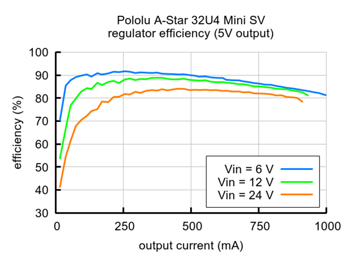
As shown in the left graph below, the SV’s switching regulator has an efficiency – defined as (Power out)/(Power in) – of 80% to 95% for most combinations of input voltage and load.
Typical efficiency of the regulator on the A-Star 32U4 Mini SV (newer ac02f version). |
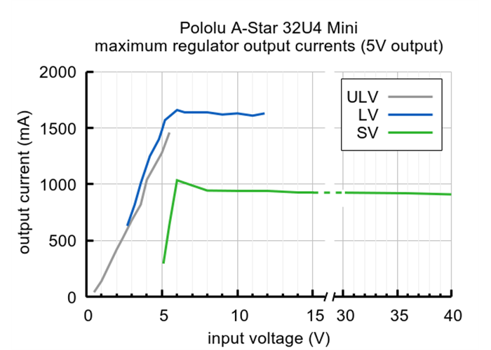
Typical maximum output current of the regulators on the A-Star 32U4 Mini boards (SV graph is of the newer ac02f version). |
The A-Star’s components, including the microcontroller and LEDs, draw 30 mA to 40 mA in typical applications. The rest of the regulator’s achievable output current, which depends on input voltage as well as ambient conditions, can be used to power other devices. The green line in the right graph above shows the output currents where the regulator’s output voltage drops below 4.75 V. These currents are close to the limits of the regulator’s capability and generally cannot be sustained for long periods; under typical operating conditions, a safe limit for the maximum continuous regulator output current is approximately 800 mA.
The dropout voltage of a step-down regulator is defined as the minimum amount by which the input voltage much exceed the regulator’s target output voltage in order to assure the target output can be achieved. As can be seen in the graph below, the dropout voltage of the Mini SV’s regulator increases approximately linearly with the output current. For light loads where the dropout voltage is small, the board can operate down to 5 V. However, for larger loads, the dropout voltage should be taken into consideration when selecting a power supply; operating above 6 V will ensure the full output current is available.
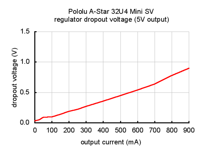
Typical dropout voltage of the 5V regulator on the A-Star 32U4 Mini SV (newer ac02f version).
Note: Batteries can have much higher voltages than their nominal voltages when fully charged, so be careful with nominal voltages above 24 V. A 36 V battery is not appropriate for this product.
This newer version (ac02f) of the A-Star 32U4 Mini SV replaces the original version (ac02c). The new version uses an improved 5 V regulator that can deliver more current (800 mA vs 500 mA) and operates to 40 V instead of 36 V. The easiest way to distinguish between the two versions is via the silkscreen on the side of the board opposite the USB connector, where the original version is labelled ac02c and the new version is labelled ac02f. The new version also uses an ENIG finish, so the plating on the exposed copper looks gold, and it has unplated mounting holes.
The A-Star 32U4 ships with a preloaded Arduino-compatible bootloader (which uses 4 KB of flash memory, leaving 28 KB available for the user program). We provide a software add-on that enables the board to be easily programmed from the Arduino environment.
The A-Star 32U4 Mini boards use the same microcontroller as the Arduino Leonardo and Arduino Micro and run at the same frequency, and they are the same size as the Arduino Micro, but they offer a number of advantages over these other ATmega32U4-based boards. Most notably, their efficient switching regulators cover a wide range of input voltages, opening up new possibilities for powering projects built around Arduino-compatible microcontroller boards. Another advantage is the power selection circuit based on the TPS2113A power multiplexer from Texas Instruments, which allows safe, seamless power switching between USB and an external source without losses from passive components like fuses or diodes along with the ability to monitor and control the selected power source. Additionally, the A* 32U4 Mini breaks out a few additional pins from the ATmega32U4 microcontroller that are not exposed on the Arduino Micro or Leonardo, and it features larger, more convenient mounting holes than the Arduino Micro.
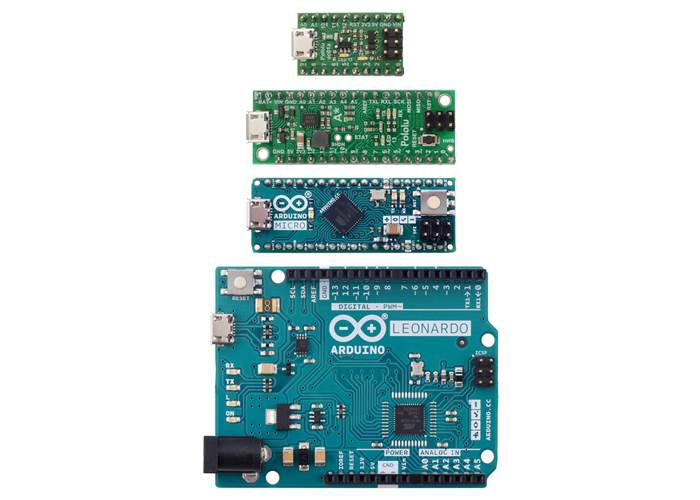
Pololu A-Star 32U4 Micro, Pololu A-Star 32U4 Mini SV, Arduino Micro, and Arduino Leonardo.
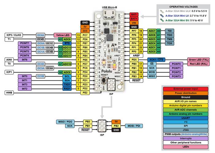
A-Star 32U4 Mini pinout diagram.
This diagram identifies the I/O and power pins on the A-Star 32U4 Mini (even though it shows the ULV version, it applies to all three A-Star Mini boards); it is also available as a printable PDF (269k pdf). For more information about the ATmega32U4 microcontroller and its peripherals, see Microchip’s ATmega32U4 documentation.
Printed on the A* circuit board are indicators that you can use to quickly identify each pin’s capabilities: a triangle next to the pin means it can be used as an analogue input, and a square wave symbol under the pin number means it can be used as a PWM output.
The A-Star 32U4 Mini can either be powered directly from the USB 5 V supply or from an external voltage source, which is regulated to 5 V by its onboard regulator, and the board’s power selection circuit enables automatic, uninterrupted transitions between the two power sources. When the A-Star is powered through an external power supply connected to the BAT+ and BAT- pins, its reverse-voltage protection circuit helps prevent it from being damaged by accidentally-reversed power connections, and the VIN pin can be used as an output to supply reverse-protected power to other devices. Alternatively, the external supply can be connected directly between VIN and GND, bypassing the reverse-voltage protection.
The A-Star 32U4 user’s guide discusses the board’s features in more detail.
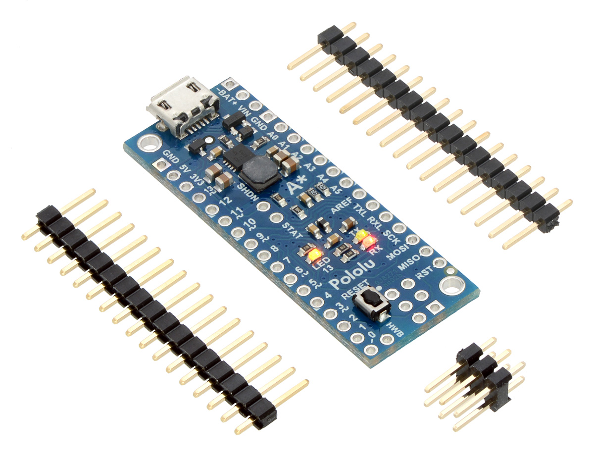
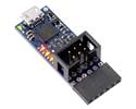
A pair of 1×17-pin breakaway 0.1″ male headers is included with the A-Star 32U4 Micro, which can be soldered in to use the board with perfboards, breadboards, or 0.1″ female connectors. Also included is a 2×3 header that can be installed to allow external programming of the microcontroller through the AVR ISP interface, such as with our USB AVR programmer. The board has two mounting holes that work with #2 and M2 screws (not included).
|
A-Star 32U4 Mini SV with soldered headers (original ac02c version shown). |
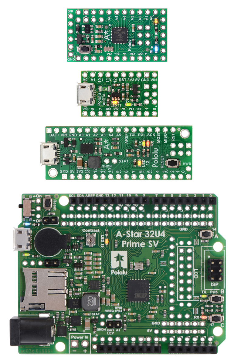 |
From top to bottom: A-Star 328PB Micro, 32U4 Micro, 32U4 Mini SV, and 32U4 Prime SV. |
|---|
The A-Star 32U4 Micro is a part of our larger A-Star family, all of whose members are based on AVR microcontrollers and are preloaded with Arduino-compatible bootloaders. The table below shows some key features and specifications of our A-Star microcontroller boards to help you choose the right one for your application.
 |
   |
  |
  | ||
|---|---|---|---|---|---|
| A-Star 328PB Micro | A-Star 32U4 Micro | A-Star 32U4 Mini ULV A-Star 32U4 Mini LV A-Star 32U4 Mini SV |
A-Star 32U4 Prime LV A-Star 32U4 Prime SV |
A-Star 32U4 Robot Controller LV A-Star 32U4 Robot Controller SV |
|
| Microcontroller: | ATmega328PB | ATmega32U4 | |||
| User I/O lines: | 24 | 18 | 26 | 26(1) | 26(1) |
| Available PWM outputs: | 9 | 6 | 7 | 7 | 7(1) |
| Analogue inputs: | 8 | 8 | 12 | 12 | 12(1) |
| Ground access points: | 6 | 2 | 4 | 43 | 44 |
| User LEDs: | 1 | 2 | 3 | 3 | 3 |
| User pushbuttons: | — | — | — | 3 | 3 |
| USB interface: |  |
|
|
|
|
| Reset button: | |
|
|
|
|
| Power switch: | |
|
|||
| Buzzer option: | |
|
|||
| microSD option: | |
||||
| LCD option: | |
||||
| Motor drivers: | |
||||
| Operating voltage: | 3.3V VCC: 3.8 V to 15 V 5V VCC: 5.5 V to 15 V |
5.5 V to 15 V | ULV: 0.5 V to 5.5 V LV: 2.7 V to 11.8 V SV: 5 V to 40 V |
LV: 2 V to 16 V SV: 5 V to 36 V |
LV: 2.7 V to 11 V SV: 5.5 V to 36 V |
| Regulator type: | 3.3 V or 5 V linear | 5 V linear | 5 V switching ULV: step-up LV: step-up/step-down SV: step-down |
5 V switching LV: step-up/step-down SV: step-down |
5 V switching LV: step-up/step-down SV: step-down |
| Regulated current:(2) | 100 mA | 100 mA | ULV: 500 mA LV: 1 A SV: 800 mA |
LV: 1.8 A SV: 1 A |
LV: 1 A SV: 1.5 A |
| Dimensions: | 1.3″ × 0.7″ | 1″ × 0.6″ | 1.9″ × 0.7″ | 2.8″ × 2.1″ | 2.6″ × 2.2″ |
| Weight: | 1.5 g(3) | 1.3 g(3) | 3.4 g(3) | 13 g to 33 g | 14 g to 23 g |
| Price: | $11.72 | $19.95 | $29.95 to $29.95 | $33.40 to $53.00 | $39.05 to $54.84 |
| 1 Some microcontroller resources are used by on-board hardware. | |||||
| 2 These values are rough approximations for comparison purposes. Available current depends on input voltage, current consumed by the board, ambient conditions, and regulator topology. See product documentation and performance graphs for details. | |||||
| 3 Without included optional headers. | |||||
| Size: | 0.7″ × 1.95″ × 0.23″1 |
|---|---|
| Weight: | 3.4 g2 |
| Processor: | ATmega32U4 @ 16 MHz |
|---|---|
| RAM size: | 2560 bytes |
| Program memory size: | 32 Kbytes3 |
| Motor channels: | 0 |
| User I/O lines: | 26 |
| Input voltage range: | 5 V to 40 V (SV) |
| Minimum operating voltage: | 5 V4 |
| Maximum operating voltage: | 40 V |
| Maximum output current: | 800 mA5 |
| Logic voltage: | 5 V |
| Reverse voltage protection?: | Y6 |
| External programmer required?: | N |
| PCB dev codes: | ac02f |
|---|---|
| Other PCB markings: | 0J11184 |
User’s manual for the Pololu A-Star 32U4 family of user-programmable boards.
Printable pinout diagram of the A-Star 32U4 Mini ULV, LV, and SV boards.
Printable schematic diagram of the A-Star 32U4 Mini ULV, LV, and SV boards.
This download contains the Windows drivers for the A-Star 32U4 and the rest of our 32U4 family of boards.
This DXF drawing shows the locations of all of the board’s holes.
This DXF drawing shows the locations of all of the board’s holes.
This DXF drawing shows the locations of all of the board’s holes.
The AStar32U4 library for the Arduino IDE helps interface with the on-board hardware on the A-Star 32U4 controllers.
This repository contains Arduino add-on files, Windows drivers, and bootloaders for the A-Star 328PB, A-Star 32U4, and the rest of our 32U4 family of boards.
Arduino integrated development environment (IDE) software
Microchip’s product page for the ATmega32U4 AVR microcontroller, with links to its datasheet, application notes, and other resources.
The web site for AVR Libc, which is the standard library of functions that you can use with C and C++ on the AVR.
The A-Star and Orangutan discussion section of the Pololu Robotics Forum.
AVR community with forums, projects, and AVR news.
AVRDUDE is a cross-platform command-line utility for programming the flash memory on AVR microcontrollers.
LUFA is an embedded software library written in C that can be used to create USB applications on USB-capable AVRs. It comes with a large library of example USB applications and bootloaders.
A free integrated development environment (IDE) for AVRs. Formerly known as Atmel Studio.
A free, open-source suite of development tools for the AVR family of microcontrollers, including the GNU GCC compiler for C/C++.
This is a library for the Arduino that interfaces with our LPS22DF, LPS25HB, LPS25H, and LPS331AP pressure/altitude sensor carriers as well as the pressure sensors on the various AltIMU-10 modules, which can be found here. It makes it simple to read the raw pressure data from the sensor, and it provides functions to help calculate altitude based on the measured pressure.
This library allows you to control an arbitrary number of SK6812/WS281x-Based Addressable RGB LEDs from an Arduino.
This is a library for the Arduino that interfaces with our LSM303D, LSM303DLHC, and LSM303DLM 3D compass and accelerometer carriers as well as the compass and accelerometer ICs on the MinIMU-9 v3 and AltIMU-10 v4 (it also works with older versions of those boards, some of which used the LSM303DLH and LSM303DLHC). It makes it simple to configure the device and read the raw accelerometer and magnetometer data, and it has a function for computing the tilt-compensated heading for those looking to use the LSM303 as a tilt-compensated compass.
This is a library for the Arduino that interfaces with our L3GD20H and L3GD20 3-axis gyro carriers as well as the gyros on the MinIMU-9 v3 and AltIMU-10 v3 (it also works with older versions of those boards, some of which used the L3G4200D and the L3GD20). It makes it simple to configure the device and read the raw gyro data.
This guide explains how to use the QTRSensors library to read Pololu QTR reflectance sensors and QTR sensor arrays with Arduinos and Arduino-compatible devices like the Pololu Orangutan robot controllers.