These small brushed DC gearmotors can deliver a lot of power for their size. This version has a 6V brushed DC motor combined with a 100:1 metal spur gearbox.
Special Order
Shipping from $9.90
+43 more from our supplier in 7-10 days
Our Code: SKU-003882
Supplier Link: [Pololu MPN:3454]
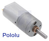
These small brushed DC gearmotors can deliver a lot of power for their size. This version has a 6V brushed DC motor combined with a 100:1 metal spur gearbox. The gearmotor is cylindrical with a diameter of 20 mm, and the D-shaped output shaft is 4 mm in diameter and extends 18 mm from the face plate of the gearbox.
Key specs at 6 V: 140 RPM and 170 mA with no load, 72 oz-in (5.2 kg-cm) and 2.9 A at stall.
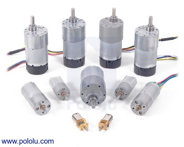
These cylindrical brushed DC gearmotors are available in a wide range of gear ratios, from 25:1 up to 488:1, and with three different motors: 6 V and 12 V motors with long-life carbon brushes (CB), and a 6 V motor with shorter-life precious metal brushes. All three motors offer similar performances at their respective nominal voltages, just with the 12 V motor drawing approximately half the current of the 6 V motor and with the carbon brush versions having longer lifetimes than the one with precious metal brushes.
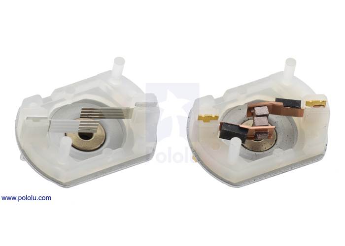
The CB versions (shown on the right in the picture below), can be differentiated from versions with precious metal brushes (shown on the left) by their copper-coloured terminals.
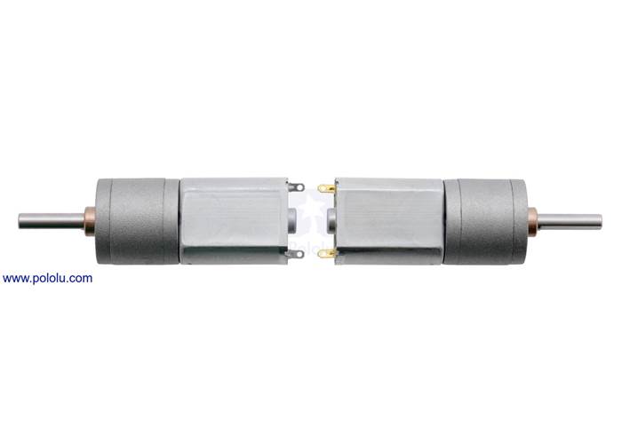
20D mm metal gearmotor with precious metal brushes (left) next to a 20D CB version with long-life carbon brushes.
20D mm metal gearmotor precious metal brushes (left) next to 20D 6V CB and 12V CB long-life carbon brushes.
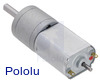
These gearmotors are optionally available with an additional 2 mm-diameter output shaft that protrudes 6 mm from the rear of the motor (see the middle picture below). This rear shaft rotates at the same speed as the input to the gearbox and offers a way to add an encoder, such as our magnetic encoder for 20D mm metal gearmotors as shown in the right picture below, to provide motor speed or position feedback.
20D mm metal gearmotor CB with long-life carbon brushes. (1) |
|
|
The gearmotors all have 20 mm diameter gearboxes and 4 mm diameter gearbox output shafts, so it is generally easy to swap one version for another if your design requirements change (though the length of the gearbox tends to increase with the gear ratio).
Please see the 20D metal gearmotor datasheet (1MB pdf) for more information, including detailed performance graphs for each 6V CB and 12V CB version. You can also use our dynamically sortable 20D metal gearmotor comparison table to search for the version that offers the best combination of speed, torque, and current draw for your particular application. A more basic comparison table is available below:
Note: Stalling or overloading gearmotors can greatly decrease their lifetimes and even result in immediate damage. In order to avoid damaging the gearbox, we recommend keeping continuously applied loads under 5 kg-cm (75 oz-in) for the versions with carbon brushes (12V CB and 6V CB) and under 3.5 kg-cm (50 oz-in) for the versions with precious metal brushes. Stalls can also result in rapid (potentially on the order of seconds) thermal damage to the motor windings and brushes, especially for motors like this that can deliver a lot of power for their size; a general recommendation for brushed DC motors is to limit continuous current to approximately 25% of the stall current.
In general, these kinds of motors can run at voltages above and below their nominal voltages; lower voltages might not be practical, and higher voltages could start negatively affecting the life of the motor.
Exact gear ratio: ``(28×28×28×28×25×25) / (14×14×14×14×10×10) = bb(100:1)``
The diagram below shows the dimensions of the 20D mm line of metal gearmotors (units are mm over [inches]). This diagram is also available as a downloadable PDF (99k pdf).
![Dimensions of the Pololu 20D mm metal gearmotors. Units are mm over [inches]. This diagram only applies to the listed gear ratios.](/cache/files/productimageoriginals/72551_0j7491.1200.jpg)
Dimensions of the Pololu 20D mm metal gearmotors. Units are mm over [inches]. This diagram only applies to the listed gear ratios.
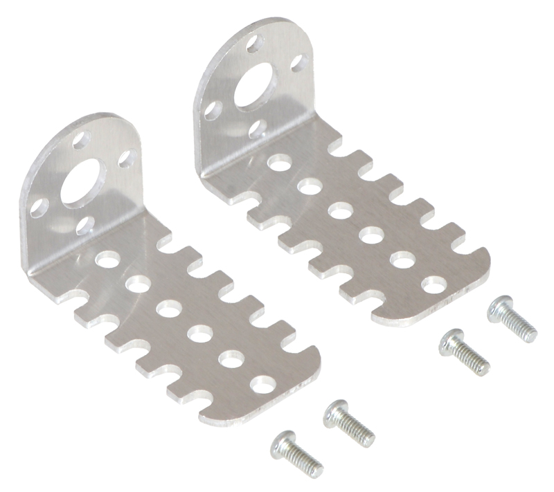
Warning: Do not screw too far into the mounting holes as the screws can hit the gears. We recommend screwing no more than 3.5 mm (0.14″) into the M2.5 mounting holes.
|
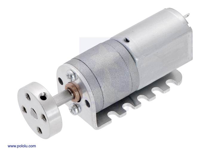
20D mm metal gearmotor with a univeral aluminum mounting hub and mounted on a 20D mm metal gearmotor bracket. |
|
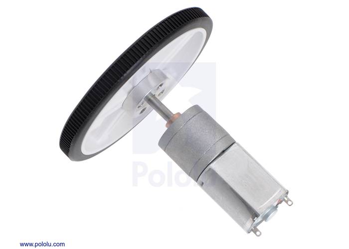
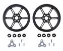
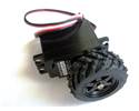
70×8mm Pololu wheel with 4mm hub adapter installed on a 20D mm metal gearmotor. |
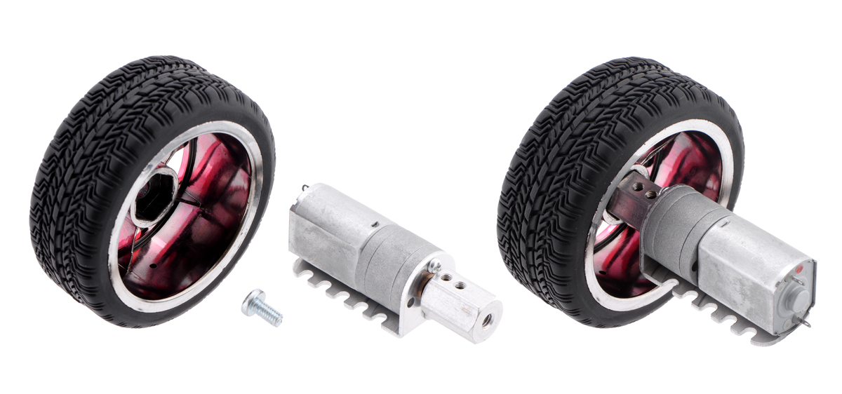
Alternatively, you could use our 4mm scooter wheel adaptor to mount many common scooter, skateboard, and inline skate wheels to the gearmotor’s output shaft as shown in the left picture below. For a general-purpose hex adaptor, consider our 12mm hex wheel adaptor, which lets you use this motor with many common hobby RC wheels as shown in the right picture below.
|
|
|
|
|
 |
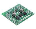
Dual TB9051FTG Motor Driver Shield for Arduino. |
|---|
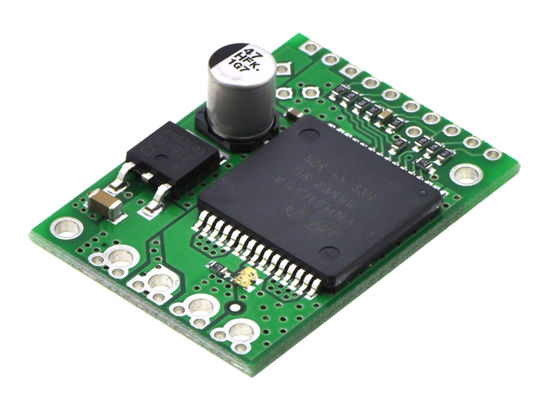 |
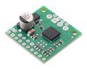
VNH5019 motor driver carrier. |
|---|
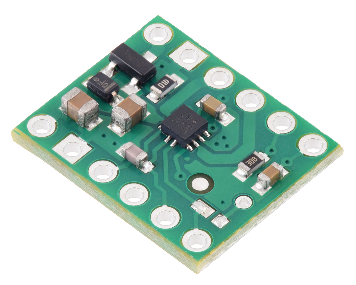 |
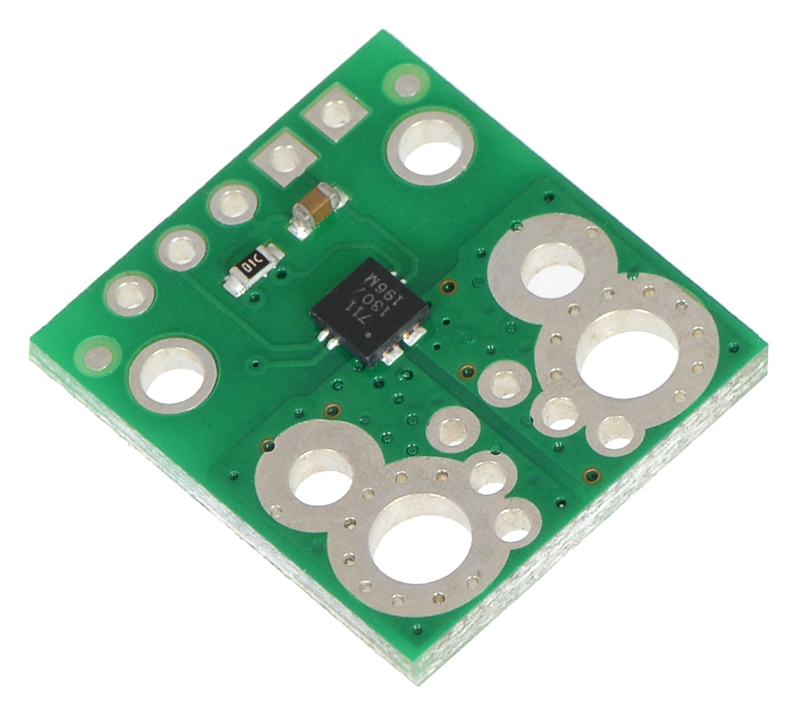
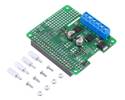
MP6550 Single Brushed DC Motor Driver Carrier. |
|---|
If you are looking for higher-level control interfaces, such as USB, RC, analogue voltages, I²C, or TTL serial, consider our Motoron motor controllers, Jrk motor controllers, or RoboClaw motor controllers; these controllers are available in various power levels several of which can handle the 20D mm metal gearmotors (we generally recommend a motor controller that can handle continuous currents above the stall current of your motor).
 |
Three Motoron M3H550 controllers being controlled by a Raspberry Pi. |
|---|
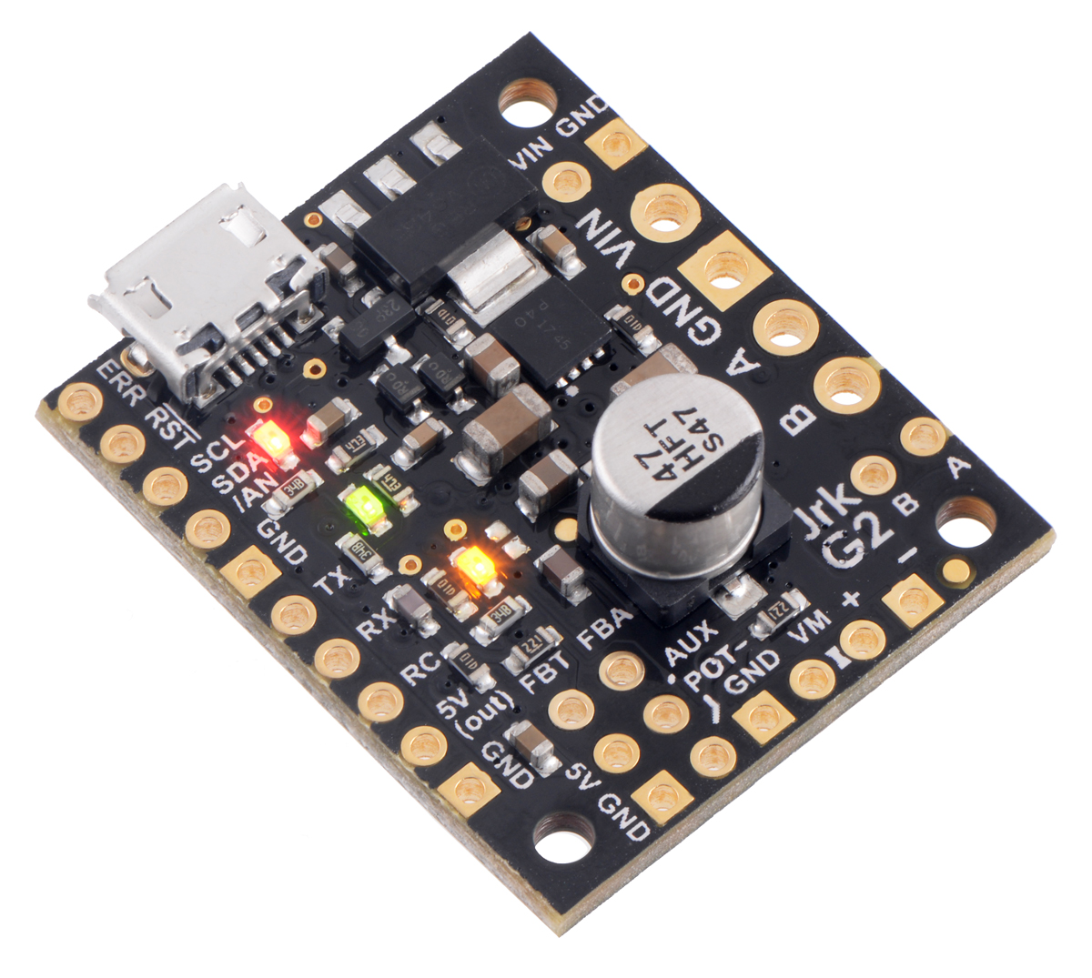 |
Jrk G2 21v3 USB Motor Controller with Feedback. |
|---|
 |
RoboClaw 2×7A Motor Controller (V5B) in its included case. |
|---|
|
|
We offer a wide selection of metal gearmotors that offer different combinations of speed and torque. Our metal gearmotor comparison table can help you find the motor that best meets your project’s requirements.
 |
| Size: | 20D × 44L mm |
|---|---|
| Weight: | 45 g |
| Shaft diameter: | 4 mm |
| Gear ratio: | 100:1 |
|---|---|
| No-load speed @ 6V: | 140 rpm |
| No-load current @ 6V: | 170 mA |
| Stall current @ 6V: | 2.9 A1 |
| Stall torque @ 6V: | 90 oz·in1 |
| Extended motor shaft?: | N |
| Motor type: | 2.9A stall @ 6V |
This file contains 3D models (in the step file format) of the 20D mm gearmotors. Note: these models only accurately represent our newer versions with 18mm-long output shafts; they are not accurate representations of the older versions with shorter output shafts (i.e. gear ratios 29:1, 56:1, 73:1, and 154:1).
No! Stalls can result in rapid (potentially on the order of seconds) thermal damage to the motor windings and brushes; a general recommendation for brushed DC motor operation is 25% or less of the stall current, which means keeping continuously applied loads around 25% or less of the stall torque.
Additionally, for many of our gearmotors with high gear ratios, the extrapolated stall torque is beyond what the gearboxes are designed to handle, and a stall could instantly damage the gears. Make sure to keep applied loads within the published limits for your gearmotor.


![Dimensions of the Pololu 20D mm metal gearmotors. Units are mm over [inches]. This diagram only applies to the listed gear ratios.](/Cache/Files/ProductImageOriginals/72551_0J7491.1200.jpg?v636600100920371319)