This power distribution board is designed specifically for the Romi chassis as a convenient way to access the chassis’s battery power and pass that on the rest of the electronics that make up your robot.
Special Order
Shipping from $9.90
+10 more from our supplier in 7-10 days
Our Code: SKU-003755
Supplier Link: [Pololu MPN:3541]
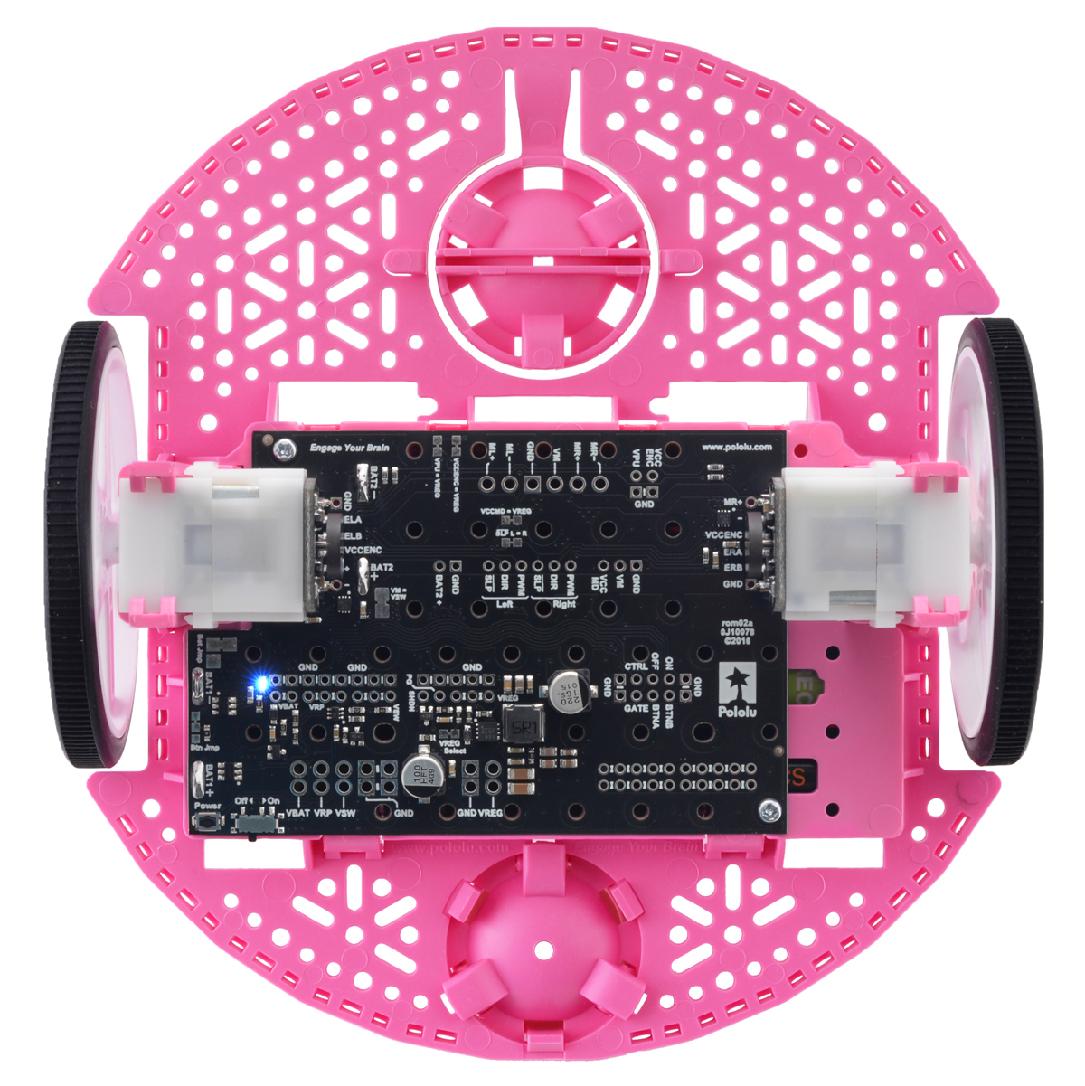
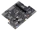
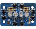
This power distribution board is designed specifically for the Romi chassis as a convenient way to access the chassis’s battery power and pass that on the rest of the electronics that make up your robot. It has slots for soldering directly to the chassis’s battery contacts offers reverse voltage protection, several power switching options, and easy access to the various power busses. Just add your own motor drivers, microcontroller, and sensors to complete your Romi robot.

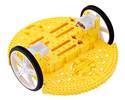
Power Distribution Board for Romi Chassis. (1)
This power distribution board is designed specifically for the Romi chassis as a convenient way to access the chassis’s battery power and pass that on to the rest of the electronics that make up your robot. The board features reverse voltage protection and the patented latching circuit from the Pololu pushbutton power switch, providing a compact, solid-state power switch for your robot that can be controlled with a momentary pushbutton: one push turns on power and another push turns it off.
The board has a small pushbutton already installed and offers convenient points for connecting external pushbutton or tactile switches in parallel. It also offers several alternate pushbutton connection options that result in push-on-only or push-off-only operation, and additional inputs enable further power control options like allowing your robot to turn off its own power. Alternatively, the board can be reconfigured to disable the pushbutton circuit and give control to the small installed slide switch.
The board’s power buses are accessible through a set of 0.1″-spaced pins that are compatible with standard 0.1″ male and 0.1″ female headers, and also through a larger set of holes that are compatible with 3.5mm-pitch terminal blocks (you can combine a 2-pin block and a 3-pin block into a single 5-pin block that spans the three power holes and two ground holes).
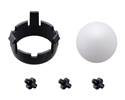
Two 1/4″ #2-56 screws and two #2-56 nuts are included for mounting the board to the Romi chassis.
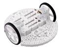
Power Distribution Board for Romi Chassis. (2) (2) |
|
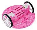
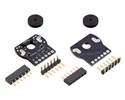
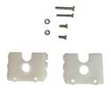
Power Distribution Board for Romi Chassis with included hardware. |
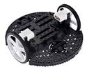
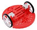
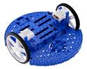
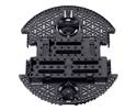
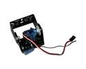
Power Distribution Board for Romi Chassis on a black chassis. |
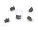
Before installing the power distribution board on a Romi chassis, you should solder any headers, terminal blocks, wires, or other connectors you plan to use on the board (not included). Please read the rest of this page carefully to determine what additional connectors you might want and where they should be installed.
It is possible to remove the board from the chassis later to solder additional connections, and some of the through holes can be soldered through the slots in the chassis while the board is mounted, but soldering beforehand is easier and avoids the risk of inadvertently melting the chassis with your soldering iron.
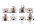
The four battery terminals should be soldered to the board after it is mounted on the chassis, as described in the chassis assembly instructions. You will be able to remove the board and battery contacts from the chassis as a single piece after soldering.
Once your you have soldered your through-hole connections to the power distribution board, please follow the instructions given in the Pololu Romi Chassis User’s Guide to finish assembling the chassis, mounting the control board, and soldering in the battery contacts. (The diagrams in those instructions show assembly with the larger Romi 32U4 Control Board, but the same steps apply for the smaller power distribution board.)
By default, the on-board pushbutton can be used to toggle power: one push turns on power and another turns it off. Alternatively, a separate pushbutton can be connected to the BTNA and BTNB pins and used instead. Multiple pushbuttons can be wired in parallel for multiple control points, and each of the parallel pushbuttons, including the one on the board itself, will be able to turn the switch on or off. The latching circuit performs some button debouncing, but pushbuttons with excessive bouncing (several ms) might not function well with it.
For proper pushbutton operation, the board’s slide switch should be left in its Off position. (Sliding the switch to the On position will cause the board power to latch on, and the switch must be returned to the Off position before the board can be turned off with the pushbutton.)
Alternatively, to disable the pushbutton, you can cut the button jumper labelled Btn Jmp; this transfers control of the board’s power to the on-board slide switch instead. A separate slide or toggle switch can be connected to the GATE pin and used instead.
More advanced control options are available through the button connection pins and four control inputs:
| PIN | Description |
|---|---|
| BTNA | Connect through momentary switch to pin “BTNB” for standard push-on/push-off operation. Connect through momentary switch to ground for on-only operation. |
| BTNB | Connect through momentary switch to pin “BTNA” for standard push-on/push-off operation. |
| ON | A high pulse (> 1 V) on this pin turns on the switch circuit. This pin only functions when pushbutton operation is enabled (i.e. the button jumper has not been cut). |
| OFF | A high pulse (> 1 V) on this pin turns off the switch circuit (e.g. allowing a powered device to shut off its own power). This pin only functions when pushbutton operation is enabled. |
| CTRL | With pushbutton operation enabled, this pin directly determines the state of the switch circuit. A high pulse (> 1 V) on this pin turns on the switch; a low pulse (e.g. driving the pin low with a microcontroller output line or pushing a button connected from this pin to ground) turns the switch off. Leave this pin disconnected or floating when not trying to set the switch state. Note that this pin should not be driven high at the same time the “OFF” pin is driven high. |
| GATE | With pushbutton operation disabled (button jumper cut), this pin controls the state of the switch circuit: driving it low turns the switch on, while letting it float turns the switch off. Connect through slide or toggle switch to ground for on/off operation. Leave this pin disconnected or floating for proper pushbutton operation. We recommend only ever driving this pin low or leaving it floating; this pin should never be driven high while the slide switch is in the “On” position. |
The diagram below shows the layout of the power distribution buses and access points on the board.

Power bus diagram of the Power Distribution Board for Romi Chassis.
The power distribution board’s default configuration provides battery power, VBAT, from all six of the chassis’s AA cells in series (nominally about 7.2 V with rechargeable batteries or 9 V with alkaline batteries). However, the board’s battery jumper, labelled Bat Jmp, allows you to reconfigure the battery connections to provide two independent supplies: BAT1, with 4 cells in series (nominally 4.8 V rechargeable or 6 V alkaline), and BAT2, with 2 cells in series (nominally 2.4 V rechargeable or 3 V alkaline). Cutting the connection between the BAT1− and BAT2+ pads separates the two sets of batteries, and using solder to bridge the BAT1− and GND pads establishes a common ground between the two new supplies.
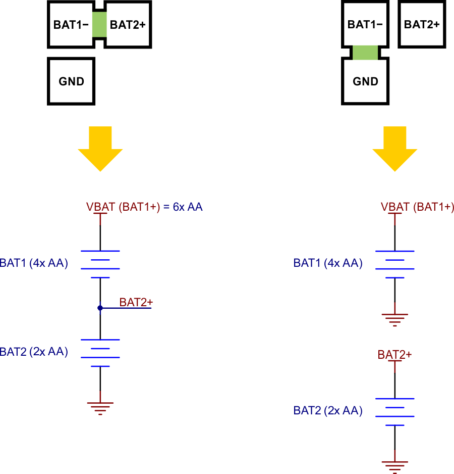 |
Warning: Do not bridge the BAT1− and GND pads without first disconnecting BAT1− from BAT2+. Failing to do so could create a short circuit across the BAT2 batteries.

Schematic diagram of the Power Distribution Board for Romi Chassis.
This schematic is also available as a downloadable pdf (110k pdf).
In addition to the power distribution board, we have a few other boards designed to mount onto a Romi chassis:
| Weight: | 6.2 g1 |
|---|
| Current rating: | 5 A |
|---|---|
| Minimum operating voltage: | 2.5 V |
| Maximum operating voltage: | 10.8 V |
| PCB dev codes: | rom01a |
|---|---|
| Other PCB markings: | 0J10031 |
This DXF drawing shows the locations of all of the board’s holes.