The Pololu Simple High-Power Motor Controller makes basic control of brushed DC motors easy, with our free Simple Motor Control Centre software enabling quick configuration over USB. The controller supports four interface modes: USB, TTL serial, analogue voltage, and hobby radio control (RC).
Special Order
Shipping from $9.90
+4 more from our supplier in 7-10 days
Our Code: SKU-002566
Supplier Link: [Pololu MPN:1379]
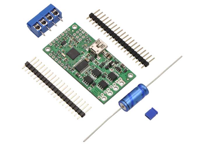
The Pololu Simple High-Power Motor Controller makes basic control of brushed DC motors easy, with our free Simple Motor Control Center software enabling quick configuration over USB. The controller supports four interface modes: USB, TTL serial, analog voltage, and hobby radio control (RC). This version operates from 5.5 to 40 V and is efficient enough to deliver a continuous 12 A without a heat sink. It ships with the power capacitor and connectors included but not soldered in, allowing for custom installations.
Not recommended for new designs: We strongly recommend our newer and better G2 SMCs (with blue PCBs), which can generally be used as drop-in replacements for these original SMCs with green PCBs. We are continuing to offer the original SMCs for now as legacy products for those with systems designed specifically for this controller.
The table below lists the all of the members of the Simple Motor Controller family and shows the key differences among them. The original SMCs are not recommended for new designs, and they are only included in the table below for comparison purposes.
| Original versions, not recommended for new designs (included for comparison purposes) |
G2 versions, released November 2018 |
||||||||
 SMC 18v7 |
 SMC 18v15 |
SMC 24v12 |
 SMC 18v25 |
SMC 24v23 |
 SMC G2 18v15 |
 SMC G2 24v12 |
 SMC G2 18v25 |
 SMC G2 24v19 |
|
|---|---|---|---|---|---|---|---|---|---|
| Minimum operating voltage: | 5.5 V | 5.5 V | 5.5 V | 5.5 V | 5.5 V | 6.5 V | 6.5 V | 6.5 V | 6.5 V |
| Recommended max operating voltage: |
24 V(1) | 24 V(1) | 34 V(2) | 24 V(1) | 34 V(2) | 24 V(1) | 34 V(2) | 24 V(1) | 34 V(2) |
| Max nominal battery voltage: |
18 V | 18 V | 28 V | 18 V | 28 V | 18 V | 28 V | 18 V | 28 V |
| Max continuous current (no additional cooling): |
7 A | 15 A | 12 A | 25 A | 23 A | 15 A | 12 A | 25 A | 19 A |
| USB, TTL serial, Analogue, RC control: |
 |
|
|
|
|
|
|
|
|
| I²C control: | |
|
|
|
|||||
| Hardware current limiting: | |
|
|
|
|||||
| Reverse voltage protection: | |
|
|
|
|||||
| Dimensions: | 2.1″ × 1.1″ | 2.3″ × 1.2″ | 2.1″ × 1.1″ | 1.7″ × 1.2″ | |||||
| Price: | $157.53 | $161.27 | $169.88 | $201.99 | $204.14 | $135.02 | $135.02 | $165.09 | $165.09 |
| Available with connectors installed? |
Yes | Yes | Yes | No | No | Yes | Yes | No | No |
| 1 30 V absolute max. 2 40 V absolute max. |
|||||||||
Simple Motor Controllers.
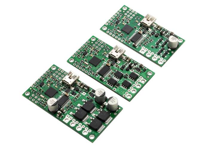
The Pololu Simple Motor Controllers (or SMC, for short) are versatile, general-purpose motor controllers for brushed, DC motors. A wide operating range of up to 5.5–40V and the ability to deliver up to several hundred Watts in a small form factor make these controllers suitable for many motor control applications. With a variety of supported interfaces—USB for direct connection to a computer, TTL serial for use with embedded systems, RC hobby servo pulses for use as an RC-controlled electronic speed control (ESC), and analogue voltages for use with a potentiometer or analogue joystick—and a wide array of configurable settings, these motor controllers make it easy to add basic control of brushed DC motors to a variety of projects. Although this motor controller has many more features than competing products, a free configuration utility (for Windows and Linux) simplifies initial setup of the device and allows for in-system testing and monitoring of the controller via USB.

Simple High-Power Motor Controller 18v25 or 24v23 simplified connection diagram.
Status tab in the Pololu Simple Motor Control Center. |
Input Settings tab in the Pololu Simple Motor Control Center. |
Note: A USB A to mini-B cable (not included) is required to connect this controller to a computer.
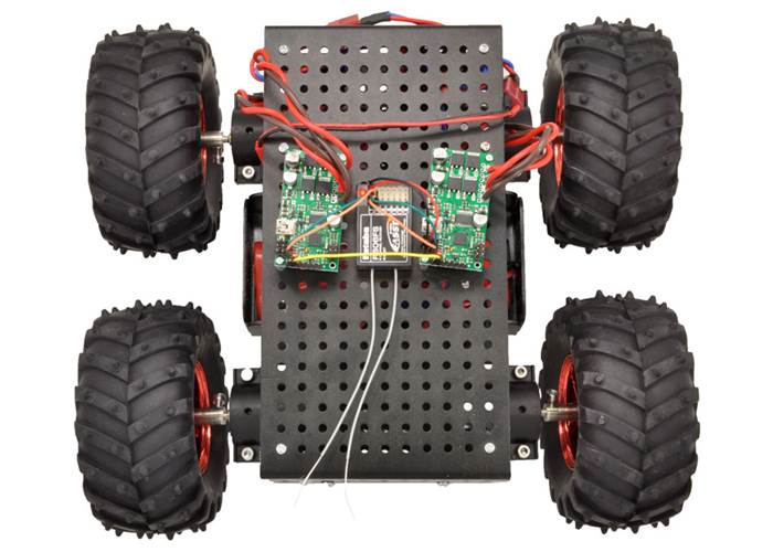
Two Pololu Simple Motor Controllers enable mixed RC-control of Dagu Wild Thumper 4WD all-terrain chassis.
This video demonstrates the versatility of the Simple Motor Controller by showing how it can be controlled directly from the analog output of a Sharp analog distance sensor—there is no intermediate control board and no programming involved. For more information on this example, including the SMC settings file and a list of parts used, see our blog post about the demo.
Simple High-Power Motor Controller 18v15 or 24v12, fully assembled. |
Simple High-Power Motor Controller 18v15 or 24v12, partial kit with included hardware. |
Most Simple Motor Controllers are available “fully assembled”, with the power capacitor and connectors pre-installed, or with these components included but not soldered in. For example, a fully assembled 18v15 ships as shown in the left picture above, and an 18v15 with included hardware ships as shown in the right picture above (the included hardware consists of a power capacitor, a 40×1 straight 0.1" male header strip, a 5mm-pitch 4-pin terminal block, and a blue shorting block).
The connector-free version allows flexibility in choice of connectors and placement of the power capacitor (e.g. on the other side of the board) to accommodate compact installations or to make room for a heat sink.
Note: The power capacitor has a significant effect on performance; the included capacitor is the minimum size recommended, and bigger ones can be added if there is space. A bigger capacitor might be required if the power supply is poor or far (more than about a foot) from the controller.
The included terminal blocks are only rated for 16 A, so we recommend soldering thick wires directly to the connector-free version of the board and using higher-current connectors for applications that will exceed the terminal blocks’ ratings.
Simple Motor Controller 18v7 bottom view with dimensions. |
Simple High-Power Motor Controller 18v15 or 24v12 bottom view with dimensions. |
Simple High-Power Motor Controller 18v25 or 24v23 bottom view with dimensions. |
Warning: Take proper safety precautions when using high-power electronics. Make sure you know what you are doing when using high voltages or currents! During normal operation, this product can get hot enough to burn you. Take care when handling this product or other components connected to it.
| Size: | 2.1" x 1.1" x 0.2" |
|---|---|
| Weight: | 7 g1 |
| Motor channels: | 1 |
|---|---|
| Control interface: |
USB; non-inverted TTL serial; RC servo pulses; analogue voltage2 |
| Minimum operating voltage: | 5.5 V |
| Maximum operating voltage: | 40 V |
| Continuous output current per channel: | 12 A3 |
| Maximum PWM frequency: | 21.77 kHz |
| Maximum logic voltage: | 3.3 V4 |
| Reverse voltage protection?: | N |
| Partial kit?: | Y |
User’s manual for the Pololu Simple Motor Controllers.
The Pololu USB SDK contains example code for making your own applications that use native USB to control the Jrk Motor Controller, Maestro Servo Controller, Simple Motor Controller, or USB AVR Programmer.
An application note about using AutoHotkey for Windows to control Pololu USB products.
This ZIP archive contains the installation files for the Simple Motor Control Centre, the Simple Motor Controller command-line utility (SmcCmd), and the required USB drivers for Microsoft Windows.
This tar/gzip archive contains the binary executable files for the Pololu Simple Motor Control Centre (SmcCenter) and the Simple Motor Controller command-line utility (SmcCmd) for Linux. Use “tar -xzvf filename.tar.gz” to extract it.
Use this file with the Pololu Simple Motor Control Centre to upgrade your Simple Motor Controller’s firmware. See the instructions in the “Upgrading Firmware” section of the user’s guide for more information.
This DXF drawing shows the locations of all of the board’s holes.
This DXF drawing shows the locations of all of the board’s holes.
This DXF drawing shows the locations of all of the board’s holes.
The analogue input readings on the Simple Motor Controller are updated approximately every 2.3 ms (435 Hz) if the “Ignore pot disconnect” option is selected. If that option is not selected, which is the default, the readings are updated half as frequently.
If no acceleration or deceleration limits are used, the outputs of the motor controller will be updated very quickly (within a few hundred microseconds) after the analogue reading is complete. If those limits are enabled, the motor might take up to a millisecond to be updated after the analogue reading is complete.