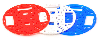
This chassis base plate is a round piece of 1/8" (3 mm) acrylic with a 5" (127 mm) diameter and cutouts for building a differential-drive robot chassis based on our micro metal gearmotors and 42×19mm wheels .
Special Order
Shipping from $9.90
+12 more from our supplier in 7-10 days
Our Code: MEC-30020
Supplier Link: [Pololu MPN:1506]
This chassis base plate is a round piece of 1/8" (3 mm) acrylic with a 5" (127 mm) diameter and cutouts for building a differential-drive robot chassis based on our micro metal gearmotors and 42×19mm wheels. The chassis has assorted general-purpose holes and slots that support many configurations of sensors and other robot components.
The 5" robot chassis RRC04A is an 1/8" acrylic chassis that provides a base for our micro metal gearmotors, extended brackets, and 42×19mm wheels. The robot chassis has many mounting holes that let you mount a variety of robot components to it. With a diameter of only five inches, this acrylic chassis is great for building robots capable of navigating tight spaces.
The RRC04A robot chassis is available in a variety of coloured (and clear) acrylics:
 |
The Pololu 5" robot chassis RRC04A is available in a variety of colors. |
|---|
Note: Note that the 1000:1 micro metal gearmotors have longer gearboxes than the other gear ratios and will only work with this chassis if you modify it to have larger wheel wells, though gearmotors like this are generally poor choices for robotic propulsion (unless your goal is to make an agonizingly slow snail robot).
You might find our premium jumper cables helpful in connecting various components.
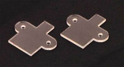
The laser-cut chassis is designed to work with the Pololu encoders. If you do not use the encoders, you can use the two included spacers that keep the chassis at the same height. The spacers are cut out of 1/16" clear acrylic.
 |
Pololu 5" round robot chassis RRC04A includes two spacers. |
|---|
Pololu 5" round robot chassis RRC04A with the motors mounted below the chassis and an Orangutan SV-328 mounted on standoffs.
The motors can be mounted on either side of the chassis (top or bottom). With the motors mounted on the bottom, the chassis will be roughly 1" from the ground, and you can use the Pololu 1" ball castor as a third point of contact with the floor. With the motors mounted on the top, the chassis will be a roughly 0.4" from the ground, making the Pololu 3/8" ball castor with the included 1/16" spacer the best fit.
There are many different ways to connect the compatible components to the chassis. You can refer to the diagram showing where compatible components can be mounted for further information about where you might mount various components. Some configurations require standoffs. You can see additional pictures of examples in the pictures tab.
| Colour: | transparent grey |
|---|