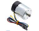
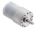
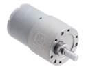
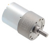
This gearmotor is a powerful brushed DC motor with 50:1 metal gearbox intended for operation at 12 V . The gearbox is composed mainly of spur gears, but it features helical gears for the first stage for reduced noise and improved efficiency.
In stock in Australia
Shipping from $9.90
+137 more from our supplier in 7-10 days
Our Code: SKU-005598
Supplier Link: [Pololu MPN:4743]
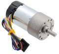
This gearmotor is a powerful brushed DC motor with 50:1 metal gearbox intended for operation at 12 V. The gearbox is composed mainly of spur gears, but it features helical gears for the first stage for reduced noise and improved efficiency. These units have a 16 mm-long, 6 mm-diameter D-shaped output shaft. This gearmotor is also available with an integrated encoder.
Key specifications:
| voltage | no-load performance | stall extrapolation |
|---|---|---|
| 12 V | 200 RPM, 200 mA | 21 kg⋅cm (290 oz⋅in), 5.5 A |
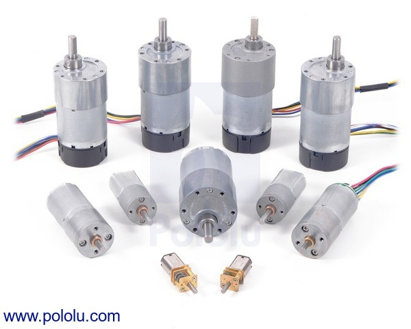
Measuring 37 mm (1.46″) in diameter, these brushed DC gearmotors are the largest and most powerful we carry. They are available in a range of gear ratios from 6.3:1 to 150:1 and with 12 V or 24 V motors, and all versions are available with integrated 64 CPR quadrature encoders on the motor shafts. The 12 V and 24 V motors offer approximately the same performance at their respective nominal voltages, with the 24 V motor drawing half the current of the 12 V motor. See the 37D metal gearmotor datasheet (2MB pdf) for more information, including detailed performance graphs for each gearmotor version. You can also use our dynamically sortable 37D gearmotor comparison table to search for the version that offers the best combination of speed, torque, and current draw for your particular application. A more basic comparison table is available below.
| Rated Voltage |
Stall Current |
No-Load Current |
Gear Ratio | No-Load Speed (RPM) |
Extrapolated Stall Torque |
Max Power (W) |
 Without Encoder |
 With Encoder |
|
|---|---|---|---|---|---|---|---|---|---|
| (kg ⋅ cm) | (oz ⋅ in) | ||||||||
| 12 V | 5.5 A | 0.2 A | 1:1 (no gearbox) | 10,000 | 0.5 | 7 | – | – | item #4750 |
| 6.3:1 | 1600 | 3.0 | 42 | 12 | item #4747 | item #4757 | |||
| 10:1 | 1000 | 4.9 | 68 | 12 | item #4748 | item #4758 | |||
| 19:1 | 530 | 8.5 | 120 | 12 | item #4741 | item #4751 | |||
| 30:1 | 330 | 14 | 190 | 12 | item #4742 | item #4752 | |||
| 50:1 | 200 | 21 | 290 | 10 | item #4743 | item #4753 | |||
| 70:1 | 150 | 27 | 380 | 10* | item #4744 | item #4754 | |||
| 100:1 | 100 | 34 | 470 | 8* | item #4745 | item #4755 | |||
| 131:1 | 76 | 45 | 630 | 6* | item #4746 | item #4756 | |||
| 150:1 | 67 | 49 | 680 | 6* | item #2829 | item #2828 | |||
| 24 V | 3 A | 0.1 A | 1:1 (no gearbox) | 10,000 | 0.55 | 8 | – | – | item #4690 |
| 6.3:1 | 1600 | 3.5 | 49 | 14 | item #4688 | item #4698 | |||
| 10:1 | 1000 | 5.5 | 76 | 14 | item #4689 | item #4699 | |||
| 19:1 | 530 | 9.5 | 130 | 13 | item #4681 | item #4691 | |||
| 30:1 | 330 | 15 | 210 | 13 | item #4682 | item #4692 | |||
| 50:1 | 200 | 23 | 320 | 12 | item #4683 | item #4693 | |||
| 70:1 | 140 | 31 | 430 | 10* | item #4684 | item #4694 | |||
| 100:1 | 100 | 39 | 540 | 8* | item #4685 | item #4695 | |||
| 131:1 | 79 | 47 | 650 | 6* | item #4686 | item #4696 | |||
| 150:1 | 68 | 56 | 780 | 6* | item #4687 | item #4697 | |||
| * Output power for these units is constrained by gearbox load limits; spec provided is output power at max recommended load of 10 kg⋅cm. | |||||||||
Note: The listed stall torques and currents are theoretical extrapolations; units will typically stall well before these points as the motors heat up. Stalling or overloading gearmotors can greatly decrease their lifetimes and even result in immediate damage. The recommended upper limit for continuously applied loads is 10 kg-cm (150 oz-in), and the recommended upper limit for instantaneous torque is 25 kg-cm (350 oz-in). Stalls can also result in rapid (potentially on the order of seconds) thermal damage to the motor windings and brushes; a general recommendation for brushed DC motor operation is 25% or less of the stall current.
In general, these kinds of motors can run at voltages above and below the nominal voltages; lower voltages might not be practical, and higher voltages could start negatively affecting the life of the motor.
The gearboxes are composed mainly of spur gears, but they feature helical gears for the first stage for reduced noise and improved efficiency:
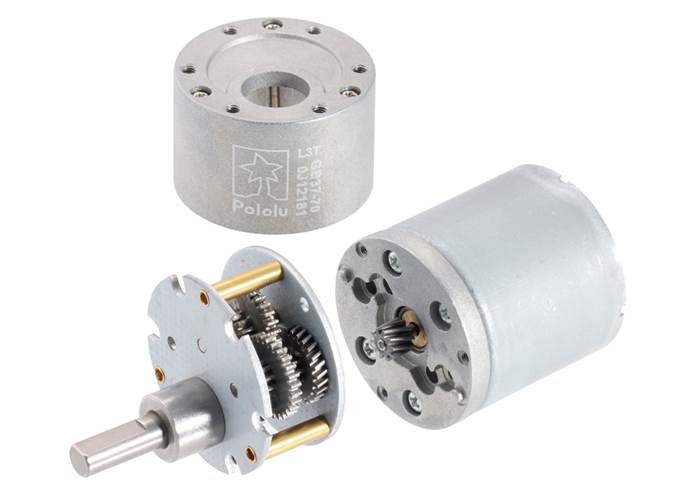
37D Gearmotor (Helical Pinion) with the gearbox removed showing the helical pinion gear and first mating gear.
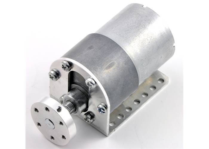
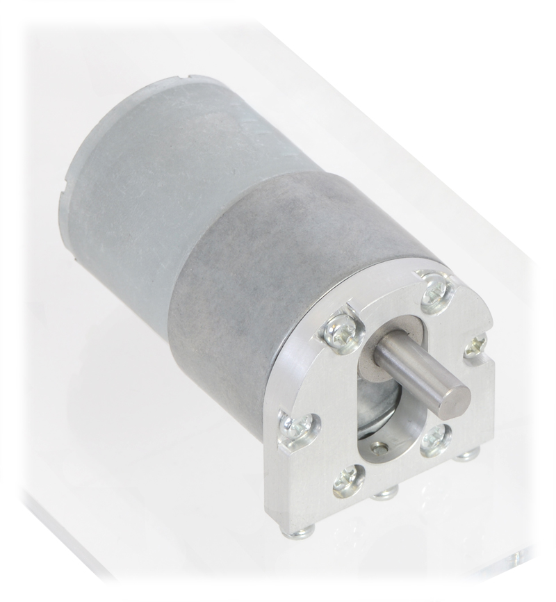
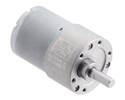
50:1 Metal Gearmotor 37Dx54L mm (Helical Pinion). |
50:1 Metal Gearmotor 37Dx54L mm (Helical Pinion). (1) |
50:1 Metal Gearmotor 37Dx54L mm (Helical Pinion). (2) (2) |
This gearmotor is a powerful brushed DC motor with 50:1 metal gearbox intended for operation at 12 V. These units have a 16 mm-long, 6 mm-diameter D-shaped output shaft. This gearmotor is also available with an integrated encoder.
Key specifications:
| voltage | no-load performance | stall extrapolation |
|---|---|---|
| 12 V | 200 RPM, 200 mA | 21 kg⋅cm (290 oz⋅in), 5.5 A |
Exact gear ratio: ``(25×30×25×40) / (10×10×15×10) =bb(50:1)``
![Dimensions of the 37D metal gearmotors (without encoders). Units are mm over [inches].](/cache/files/productimageoriginals/78975_0j10506.1200.jpg)
Dimensions of the 37D metal gearmotors (without encoders). Units are mm over [inches].
This diagram is also available as a downloadable PDF (459k pdf).
Warning: Do not screw too far into the mounting holes as the screws can hit the gears. We recommend screwing no more than 3mm (0.12″) into the screw hole.
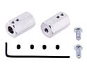
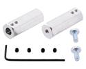
37D mm gearmotor (without encoder) with L-bracket and 6mm universal mounting hub. (2) (2) |
|
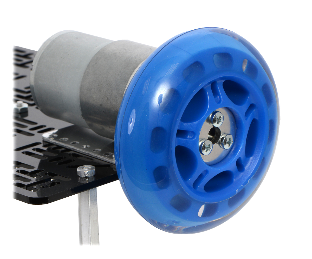
Black Pololu Wheel 90×10mm on a Pololu 37D mm Metal Gearmotor. |
|
For a general-purpose hex adaptor, consider our 12mm hex wheel adaptor (also available in an extended version), which lets you use these motors with many common hobby RC wheels.
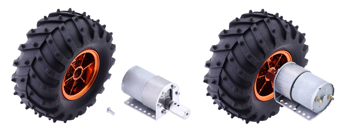 |
12mm Hex Wheel Adaptor for 6mm Shaft connecting a Wild Thumper Wheel to a 37D mm Metal Gearmotor. |
|---|
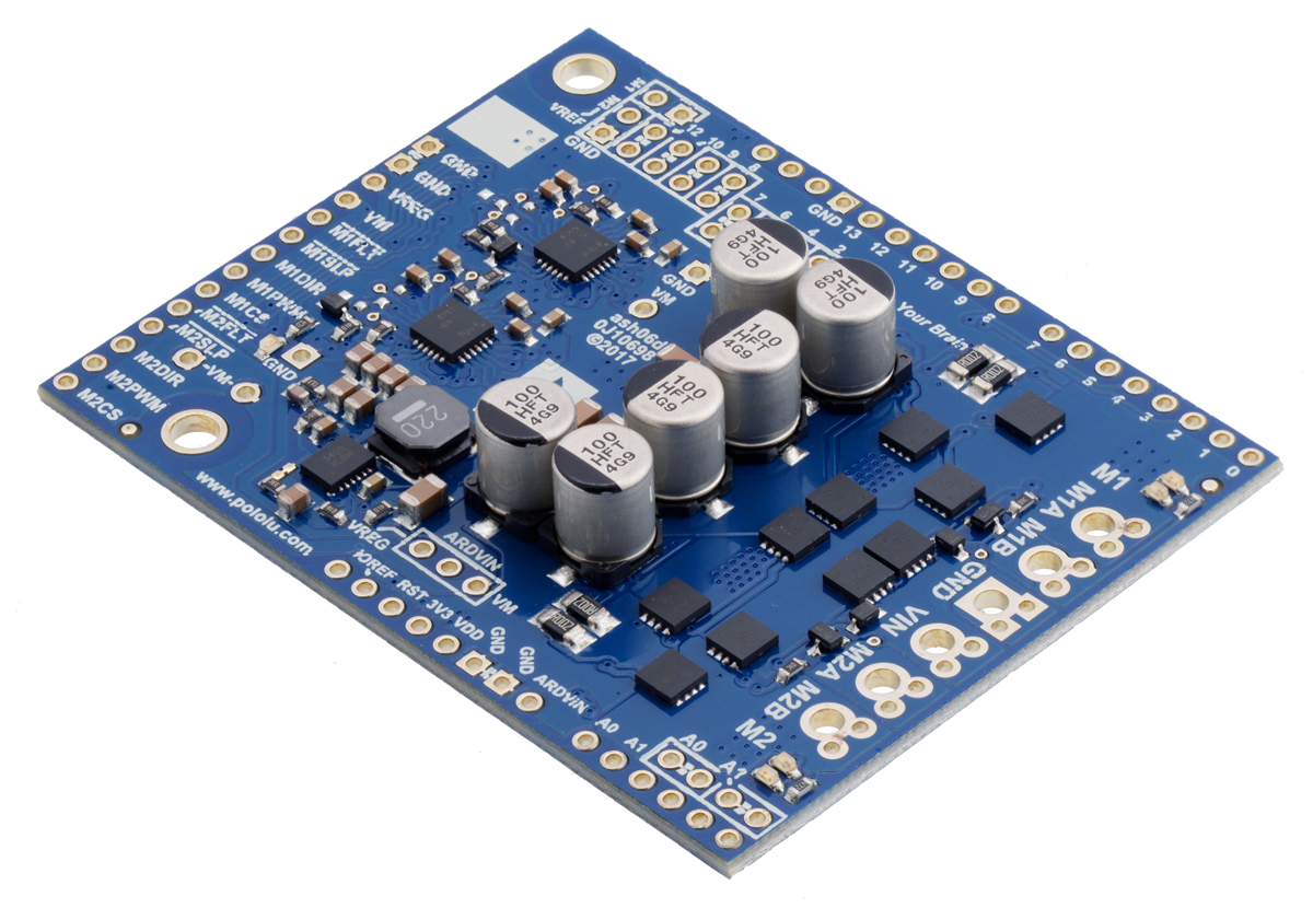 |
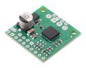
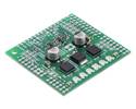
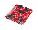
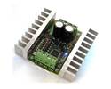
Pololu Dual G2 High-Power Motor Driver 24v14 Shield for Arduino. |
|---|
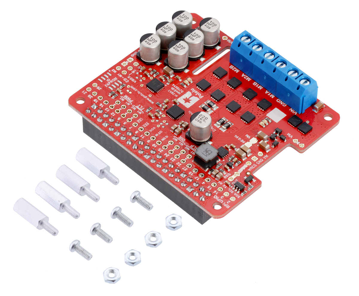 |
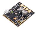
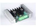
Pololu Dual G2 High-Power Motor Driver 24v14 for Raspberry Pi (assembled version) with included hardware. |
|---|
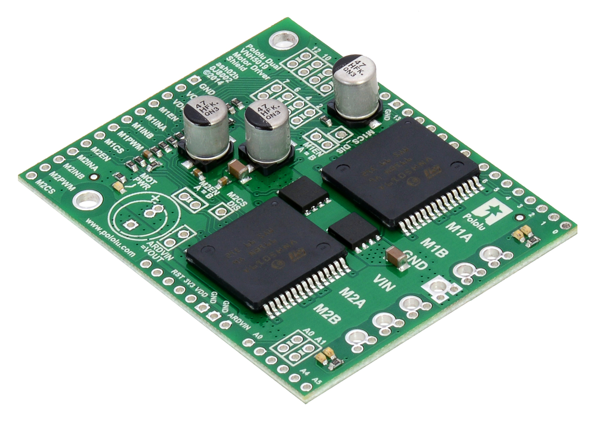 |
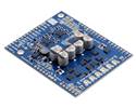
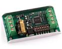
Pololu dual VNH5019 motor driver shield for Arduino. |
|---|
If you are looking for higher-level control interfaces, such as USB, RC, analogue voltages, I²C, or TTL serial, consider our Motoron motor controllers, Jrk motor controllers, or RoboClaw motor controllers; these controllers are available in various power levels several of which can handle the 37D mm metal gearmotors (we generally recommend a motor controller that can handle continuous currents above the stall current of your motor).
 |
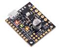
Motoron M2S18v18 Dual High-Power Motor Controller Shield for Arduino (Connectors Soldered). |
|---|
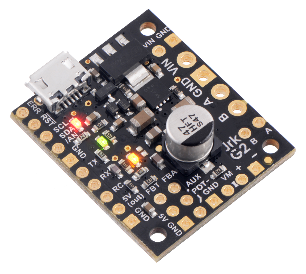 |
Jrk G2 21v3 USB Motor Controller with Feedback. |
|---|
 |
RoboClaw 2×7A Motor Controller (V5B) in its included case. |
|---|
|
|
We offer a wide selection of metal gearmotors that offer different combinations of speed and torque. Our metal gearmotor comparison table can help you find the motor that best meets your project’s requirements.
 |
| Size: | 37D × 54L mm1 |
|---|---|
| Weight: | 190 g |
| Shaft diameter: | 6 mm2 |
| Gear ratio: | 50:1 |
|---|---|
| No-load speed @ 12V: | 200 rpm |
| No-load current @ 12V: | 0.2 A |
| Stall current @ 12V: | 5.5 A3 |
| Stall torque @ 12V: | 21 kg·cm3 |
| Max output power @ 12V: | 10 W |
| No-load speed @ 6V: | 100 rpm4 |
| No-load current @ 6V: | 0.15 A4 |
| Stall current @ 6V: | 3.0 A4 |
| Stall torque @ 6V: | 12 kg·cm4 |
| Motor type: | 12V |
| Max efficiency @ 12V: | 51 % |
|---|---|
| Speed at max efficiency: | 180 rpm |
| Torque at max efficiency: | 2.2 kg·cm |
| Current at max efficiency: | 0.66 A |
| Output power at max efficiency: | 4.0 W |
| Encoders?: | N |
|---|
This file contains 3D models (in the step file format) of the 37D mm gearmotors with and without encoders.
This MATLAB script, written by Ali Asgher Mansoor Habiby, plots speed, power, current draw, and efficiency as they vary with torque when you input the gearmotor specifications. It also prints the resistance of the motor, and the current draw and torque at which maximum efficiency and maximum power occur.
No! Stalls can result in rapid (potentially on the order of seconds) thermal damage to the motor windings and brushes; a general recommendation for brushed DC motor operation is 25% or less of the stall current, which means keeping continuously applied loads around 25% or less of the stall torque.
Additionally, for many of our gearmotors with high gear ratios, the extrapolated stall torque is beyond what the gearboxes are designed to handle, and a stall could instantly damage the gears. Make sure to keep applied loads within the published limits for your gearmotor.


![Dimensions of the 37D metal gearmotors (without encoders). Units are mm over [inches].](/Cache/Files/ProductImageOriginals/78975_0J10506.1200.jpg?v636600100920371319)