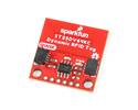
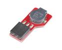
Simplify 125kHz RFID integration with this Qwiic-enabled, I2C-based breakout board that automatically buffers up to 20 timestamped scans for easy retrieval.
In stock in Australia
Shipping from $4.90
Our Code: SKU-005348
Supplier Link: [SparkFun MPN:15191]
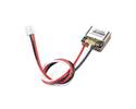
The SparkFun RFID Qwiic Reader takes the hassle out of integrating low-frequency 125kHz RFID scanning into your projects. Designed as an easy-to-use I2C breakout board for the ID-3LA, ID-12LA, and ID-20LA reader modules from ID Innovations, it eliminates the need for complex serial parsing. Simply plug a compatible reader into the socket, attach a Qwiic cable, connect the Qwiic RFID reader's INT pin, and you are ready to scan.
While most ID Innovations modules have an internal antenna, ID-3XX modules will likely require an external antenna to function. Users should consult with the module's datasheet before purchasing.
Utilising an onboard ATtiny84A microcontroller, this breakout does the heavy lifting for you. When a 125kHz RFID card is scanned, the board captures the six-byte ID tag, attaches a precise timestamp, and places it on an internal stack that safely holds up to 20 unique scans at once. This stored information is then easily accessible using simple I2C commands, freeing up your main microcontroller to focus on other tasks.

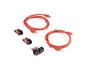
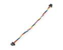
Thanks to the Qwiic connect system, you can supply 3.3V power and communicate with the board without soldering. While the I2C data flows cleanly through the Qwiic cable, you'll still need to solder or connect the interrupt pin if you decide to use that to indicate when an RFID card has been read.
Be aware that a multiplexer (Mux) is required to communicate with multiple RFID Readers on a single bus. If you need to use more than one RFID Reader sensor, consider using the Qwiic Mux Breakout.
Whether you are building an automated access control system or an interactive display, this board provides a dependable way to incorporate RFID tracking into your Qwiic I2C system.
INTBUZZERI2CADR