This powerful motor controller makes closed-loop speed or position (but not both!) control of a brushed DC motor easy, with quick configuration over USB using our free software.
Special Order
Shipping from $9.90
+68 more from our supplier in 7-10 days
Our Code: SKU-004640
Supplier Link: [Pololu MPN:3147]
This powerful motor controller makes closed-loop speed or position (but not both!) control of a brushed DC motor easy, with quick configuration over USB using our free software. It supports five control interfaces: USB, TTL serial, I²C, analog voltage (potentiometer), and hobby radio control (RC). This version offers a wide 6.5 V to 40 V operating range and can deliver continuous output currents up to 13 A without a heat sink. Male headers and terminal blocks are included but not soldered, allowing for custom installations.
With integrated support for analog voltage or tachometer (frequency) feedback, the second-generation G2 family of Jrk motor controllers makes it easy to add closed-loop control of speed or position (but not both!) of a single brushed DC motor to a variety of projects. These versatile, general-purpose modules support five different control interfaces: USB for direct connection to a computer, TTL serial and I²C for use with a microcontroller, RC hobby servo pulses for use in an RC system, and analog voltages for use with a potentiometer or analog joystick. They also offer many settings that can be configured using our free configuration software utility for Windows, Linux, and macOS. This software simplifies initial setup of the device and allows for in-system testing and monitoring of the controller via USB (a micro-B USB cable is required to connect the Jrk G2 to a computer).

Side-by-side comparison of the different Jrk G2 USB Motor Controllers with Feedback.
The table below lists the members of the Jrk family, including the original (green) versions, and shows the key differences among them.
 Jrk 21v3 |
 Jrk G2 21v3 |
 Jrk G2 18v19 |
 Jrk G2 24v13 |
 Jrk G2 18v27 |
 Jrk G2 24v21 |
|
|---|---|---|---|---|---|---|
| Recommended max operating voltage: |
28 V(1) | 28 V(1) | 24 V(2) | 34 V(3) | 24 V(2) | 34 V(3) |
| Max nominal battery voltage: |
24 V | 24 V | 18 V | 28 V | 18 V | 28 V |
| Max continuous current (no additional cooling): |
2.5 A* | 2.6 A | 19 A | 13 A | 27 A | 21 A |
| USB, TTL serial, Analogue, RC control: |
 |
|
|
|
|
|
| I²C control: | |
|
|
|
|
|
| Hardware current limiting: | |
|
|
|
||
| Dimensions: | 1.35″ × 1.35″ | 1.0″ × 1.2″ | 1.4″ × 1.2″ | 1.7″ × 1.2″ | ||
| Price: | $74.95 | $54.95 | $109.95 | $109.95 | $149.95 | $149.95 |
| 1 Transient operation (< 500 ms) up to 40 V. 2 30 V absolute max. 3 40 V absolute max. * Reduced from “3 A” based on newer, more stringent tests. The value now is directly comparable to the rating for the newer G2 21v3. |
||||||

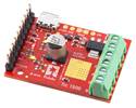
Pololu Jrk G2 18v19 USB Motor Controller with Feedback controlling an industrial-duty linear actuator with an RC receiver.

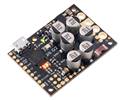
Pololu Jrk G2 18v27 USB Motor Controller with Feedback controlling a high-power motor from USB.

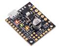
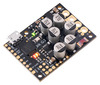
Basic pinout diagram of the Jrk G2 24v13 USB Motor Controller with Feedback.
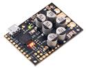
The Jrk G2 24v13 operates from 6.5 V to 40 V and can deliver a continuous output current of 13 A without a heat sink. Note that 40 V is the absolute maximum for this controller; the maximum recommended operating voltage is 34 V, and the maximum recommended nominal battery voltage is 28 V.
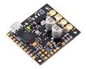
If you need to identify which version you have, you can just plug it into a computer through USB and the Jrk software will tell you. For quick visual identification without a computer, you can distinguish this version from the identically sized Jrk G2 18v19 by the number 100 on top of the tall silver electrolytic capacitors.
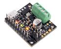
Jrk G2 24v13 USB Motor Controller with Feedback with included hardware. |
Jrk G2 18v19 or 24v13 USB Motor Controller with included terminal blocks and headers soldered. (1) |
The Jrk ships with a 0.1″ breakaway male header strip and two 2-pin 5mm terminal blocks. You can solder the terminal blocks to the four large through-holes to make your motor and motor power connections (see our short video on terminal block installation), or you can solder an 8-pin piece of the 0.1″ header strip into the smaller through-holes that border these larger holes. Note, however, that the terminal blocks are only rated for 16 A, and each header pin pair is only rated for a combined 6 A, so for higher-power applications, thick wires should be soldered directly to the board.
Pieces from the 0.1″ header strip can be soldered into the small holes on the logic connection side of the board to enable use with solderless breadboards, perfboards, or 0.1″ connectors, or you can solder wires directly to these holes for the most compact installation.
Note: A USB A to micro-B cable (not included) is required to connect the Jrk G2 to a computer for initial configuration.
The Jrk G2 family features a number of improvements compared to our original two Jrk motor controllers (21v3 and 12v12). Most importantly, the Jrk G2 controllers support both higher operating voltages and larger output currents while being even more compact than their predecessors. Other new features include:
 |
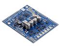
Comparison of the newer Jrk G2 21v3 (black PCB) with the original Jrk 21v3 (green PCB). |
|---|
The Jrk G2 controllers are not drop-in replacements for the original Jrk controllers because of differences in their form factors and pin arrangements, although wiring changes should be straightforward. The Jrk G2 serial protocol is compatible with (and generally a superset of) the original Jrk serial protocol, so in many cases, serial interface software running on a microcontroller or computer will not need to be modified to work with a Jrk G2.
| Size: | 1.2″ × 1.4″ × 0.42″1 |
|---|---|
| Weight: | 6.5 g1 |
| Motor channels: | 1 |
|---|---|
| Control interface: |
USB; non-inverted TTL serial; I²C; RC servo pulses; analogue voltage |
| Minimum operating voltage: | 6.5 V |
| Maximum operating voltage: | 40 V2 |
| Continuous output current per channel: | 13 A3 |
| Maximum PWM frequency: | 20 kHz |
| Reverse voltage protection?: | Y |
| Version: | G2 24v13 (40 V max, 13 A max continuous) |
| Connectors soldered?: | N |
| PCB dev codes: | umc05a |
|---|---|
| Other PCB markings: | 0J11042, blank white box |
User’s manual for the Pololu Jrk G2 USB Motor Controllers with Feedback.
This DXF drawing shows the locations of all of the board’s holes.
This DXF drawing shows the locations of all of the board’s holes.
This DXF drawing shows the locations of all of the board’s holes.
This is a library for the Arduino IDE that helps interface with a Jrk G2 USB Motor Controller with Feedback using serial or I²C.
This repository contains the source code of the Pololu Jrk G2 Configuration Utility (jrk2gui) and the Pololu Jrk G2 Command-line Utility (jrk2cmd). It also has drivers for Windows and build instructions.