This USB-to-I²C adaptor enables a PC or other USB host to act as the controller on an I²C bus, reading and writing data from I²C target devices connected to the bus. It supports clock stretching and I²C clock speeds in excess of 1 MHz.
Special Order
Shipping from $4.90
+196 more from our supplier in 7-10 days
Our Code: SKU-010799
Supplier Link: [Pololu MPN:5397]
This USB-to-I²C adapter enables a PC or other USB host to act as the controller on an I²C bus, reading and writing data from I²C target devices connected to the bus. It supports clock stretching and I²C clock speeds in excess of 1 MHz. The adapter features complete galvanic isolation between the USB and I²C sides, which prevents unexpected current flow between the two sides and protects the computer and its USB ports from destructive voltages on the I²C bus. This version delivers isolated power to the I²C side at 5V or 3.3V (selectable by an integrated switch with the state latched at start-up).
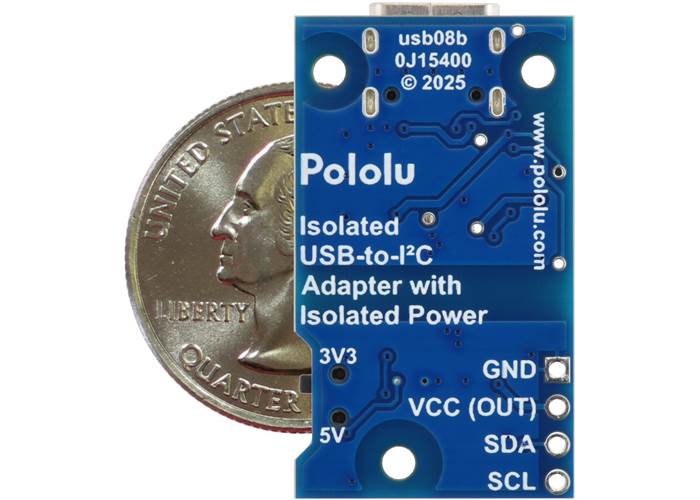
Pololu Isolated USB-to-I²C Adapter with Isolated Power, bottom view with US quarter for size reference.
This USB-to-I²C adaptor functions as a bridge between I²C devices and a PC or other USB host, enabling the USB host to serve as an I²C controller and communicate with target devices on the I²C bus. It supports bidirectional communication with clock stretching and I²C clock speeds beyond 1000 kHz.
The adaptor provides full galvanic isolation between the USB and I²C sides while optionally providing isolated and regulated 5 V or 3.3 V power at up to 200 mA to the I²C bus. This isolation prevents unexpected current flow between the USB host and the I²C bus and protects the USB host from damaging voltages on the I²C bus (the adaptor would be damaged under such conditions, but those voltages would not be able to propagate through to the USB side).
The module features a USB Type-C connector. On the USB side, the adaptor acts as a virtual serial port (CDC ACM), so it is recognised by major operating systems (e.g. Windows 10 and later, Linux, and macOS) without requiring any driver installation. This means the adaptor can be used with any programming environment that allows writing and reading binary data from a serial port (see the user’s guide for documentation on the communication protocol). We provide a Python library for the adaptor to make it easy to get started in Python, and the firmware for the adaptor’s STM32C071G8 microcontroller is open source for those who want to understand better how it works or customise the behaviour.
The I²C side features a JST SH-style 4-pin connector that works with our 4-pin JST SH-style cables and is compatible with SparkFun’s Qwiic and Adafruit’s STEMMA QT. It also brings the four I²C pins out to 0.1″-pitch through-holes that are compatible with standard 0.1″ male headers and female headers.
Note: An alternative adaptor version is available that does not deliver power from the target and instead requires target power to be supplied separately.

Pololu Isolated USB-to-I²C Adapter with Isolated Power pinout and LEDs.
| Pin | Cable colour | Function |
|---|---|---|
| 1 | Black | I²C ground (GND); this pin is NOT connected to USB GND |
| 2 | Red | I²C output voltage (VCC) — When VCC is enabled (controllable by the “Enable VCC Out” command), this pin supplies 3.3V or 5V power at up to 200 mA to the I²C bus. The voltage level is set by the position of the slide switch at start-up. |
| 3 | Blue | I²C data line (SDA) |
| 4 | Yellow | I²C clock line (SCL) |
The VCC voltage level is selectable via a slide switch on the board and latched at power-up, so changing the switch state while the board is powered will not have any effect until the board is power-cycled or enable is toggled via the “Enable VCC Out” command. You can use the blue (5V) and green (3.3V) output voltage indicator LEDs to identify the voltage level that is being output as those illuminate based on the actual voltage rather than the switch position. Both voltage level indicator LEDs are off when VCC is disabled.

Schematic diagram of the Pololu Isolated USB-to-I²C Adapter with Isolated Power.
| Size: | 1.33″ × 0.76″ × 0.19″ |
|---|---|
| Weight: | 3.2 g |
| PCB dev codes: | usb08b |
|---|---|
| Other PCB markings: | 0J15400 |
User’s manual for the Isolated USB-to-I²C Adaptor.
This DXF drawing shows the locations of all of the board’s holes.