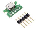
This USB-to-serial adaptor lets you easily connect a TTL serial device to a PC by acting as a virtual serial port. The board is a Micro-USB carrier for the Silicon Labs CP2102N USB-to-UART bridge that provides access to all of its control signal pins and GPIO pins.
In stock in Australia
Shipping from $4.90
+97 more from our supplier in 7-10 days
Our Code: SKU-006894
Supplier Link: [Pololu MPN:1317]
This USB-to-serial adapter lets you easily connect a TTL serial device to a PC by acting as a virtual serial port. The board is a Micro-USB carrier for the Silicon Labs CP2102N USB-to-UART bridge that provides access to all of its control signal pins and GPIO pins.

CP2102N USB-to-serial adapter carrier, bottom view with dimensions.
This USB-to-serial adaptor is a breakout board for the Silicon Labs CP2102N USBXpress USB-to-UART bridge, and it is a great solution for connecting microcontroller projects and other logic-level serial devices to a personal computer. The tiny unit measures only 0.6″ × 0.95″ including its Micro-USB connector. It offers several options for accessing the data, control, and GPIO pins on the CP2102N, all of which are made available on a 0.1″ spacing.
This board uses 3.3 V signal levels by default, but the signal pins can tolerate higher voltages, allowing the adaptor to be used with 5 V systems that see 3.3 V as a logic high. The green LED on the SUSPEND line indicates an active USB connection when lit.
The adaptor looks like a standard virtual serial port (COM port) to the computer’s operating system, which means it can be used with any software designed to work with a serial port (even a legacy RS-232 port). The CP2102N is a full-speed USB 2.0 device and allows baud rates of up to 3 Mbps. Drivers are available from Silicon Labs for Windows XP, Windows Vista, Windows 7, Windows 8, Windows 10, Linux, and Mac OS X.
This product requires a USB A to Micro-B cable (not included) to connect to a computer.
If you do not need access to all of the serial control signals, consider the Pololu USB AVR Programmer v2.1 as an alternative. In addition to its functionality as an AVR programmer, it can be used as a USB-to-TTL serial adaptor with two configurable serial handshaking lines and support for both 3.3 V and 5 V operation.
For most applications, this CP2102N carrier can be considered a drop-in replacement for our older CP2104 USB-to-Serial Adaptor Carrier with a few improvements like a higher maximum baud rate and re-programmable configuration ROM.

CP2102N USB-to-serial adapter carrier, labeled pinout.
| Pin | Type | Function |
|---|---|---|
| VDD | Power | 3.3 V voltage regulator output |
| VBUS | Power | USB bus voltage (5 V) |
| GND | Power | Ground |
| RST | In | Device reset |
| TX | Out | Asynchronous serial data transmit (idle high) |
| RX | In | Asynchronous serial data receive |
| CTS | In | “Clear to send” control input (often used with RTS) |
| RTS | Out | “Ready to send” control output (often used with CTS) |
| DSR | In | "Data set ready" control input (active low) (often used with DTR) |
| DTR | Out | "Data terminal ready" control output (active low) (often used with DSR) |
| DCD | In | "Data carrier detect" control input (active low) |
| RI | In | "Ring indicator" control input (active low) |
| SUSPEND | Out | Driven high when in USB suspend state |
| SUSPEND | Out | Driven low when in USB suspend state (connected to green LED) |
| GPIO.0 | I/O | User-configurable inputs or outputs |
| GPIO.1 | ||
| GPIO.2 | ||
| GPIO.3 |
All of the adaptor’s pins are available in two rows spaced 0.5″ apart along the sides of the board. This allows any pin to be accessed easily while the adaptor is plugged into a solderless breadboard, as shown in the left picture below.
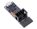
Alternatively, a 1×6 header can be soldered to the end of the board, as shown in the right picture below. This gives access to six signals (RTS, RX, TX, VBUS, CTS, and GND) that are commonly found on FTDI cables and other similar USB-to-serial adapters. As a result, this CP2102N adaptor board can be used as a drop-in replacement for an FTDI cable in many applications, such as programming Arduino-compatible boards.
CP2102N USB-to-serial adapter carrier in a breadboard with included 0.1″ male headers installed. |
CP2102N USB-to-serial adapter carrier with included 6-pin 0.1″ right-angle female header installed. |
The carrier board ships with a 1×25 straight male header strip, a 1×6 right-angle male header strip, and a 1×6 right-angle female header as shown below. You can also solder wires directly to the pads for the smallest installation.

CP2102N USB-to-serial adapter carrier with included optional headers.

VIO=VDD SMT jumper on the bottom of the CP2102N USB-to-serial adapter carrier.
This carrier board connects the VIO pin of the CP2102N to VDD by default, setting its logic voltage level to the 3.3 V provided by the IC’s built-in voltage regulator. If you want to use a lower logic voltage, you can disconnect VIO from VDD by cutting the thin trace between the two pads of the surface-mount jumper shown to the right. You can then solder a thin wire to the exposed via labelled “VIO” and connect it to a separate voltage supply (as low as 1.71 V).
Warning: We do not recommend externally supplying VIO to this board while it is not connected to USB, as this can cause it to draw excessive current (up to a few hundred milliamps).

Schematic diagram of the CP2102N USB-to-serial adapter carrier.
This schematic is also available as a downloadable PDF (169k pdf).
You do not need to be familiar with details of the CP2102N to use this board as a basic USB-to-serial adaptor, but the CP2102N also has specialised features including four general-purpose I/O (GPIO) pins and the ability to be customised by configuring its internal EEPROM. For advanced users interested in these features, we recommend careful reading of the CP2102N datasheet (619k pdf). Additional resources, including application notes referenced by the datasheet, can also be found on the CP2102N product page on the Silicon Labs website.
| Size: | 0.6″ × 0.95″ × 0.17″1 |
|---|---|
| Weight: | 1.4 g2 |
| Baud: | 300 bps–3 Mbps |
|---|
| PCB dev codes: | usb03b |
|---|---|
| Other PCB markings: | 0J13036 |
This DXF drawing shows the locations of all of the board’s holes.
Drivers for CP210x USB-to-UART bridge ICs on the Silicon Labs website.
Product information, including documentation, application notes, and configuration software, for CP2102N USBXpress USB bridge ICs on the Silicon Labs website.