This breakout board for TI’s DRV8434S microstepping bipolar stepper motor driver operates from 4.5 V to 48 V and can deliver up to approximately 1.2 A continuous per phase without a heat sink or forced air flow (2 A peak).
Special Order
Shipping from $4.90
+307 more from our supplier in 7-10 days
Our Code: SKU-009463
Supplier Link: [Pololu MPN:3768]
This breakout board for TI’s DRV8434S microstepping bipolar stepper motor driver operates from 4.5 V to 48 V and can deliver up to approximately 1.2 A continuous per phase without a heat sink or forced air flow (2 A peak). The SPI interface allows configuration of the current limit, step mode (11 step modes from full-step through 1/256-step), decay mode, and stall detection. The driver also features built-in protection against under-voltage, over-current, and over-temperature conditions. This version of has the maximum current limit set to a fixed 2A, and SPI can be used to set the actual current limit to any of 16 evenly spaced values from 125 mA up to 2 A (i.e. in increments of 125 mA).
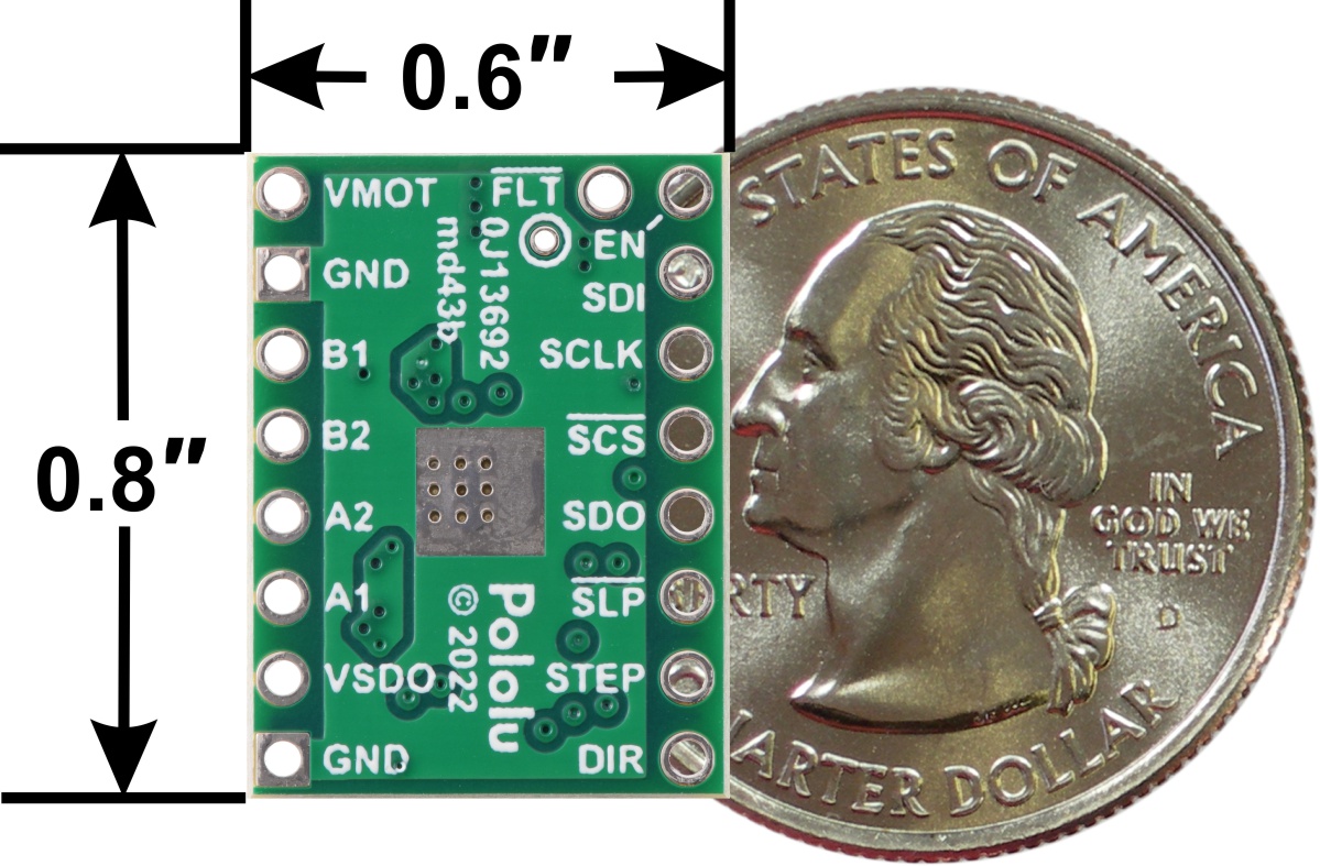 |
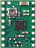
DRV8434S SPI Stepper Motor Driver Carrier, Potentiometer for Max. Current Limit, bottom view with dimensions. |
|---|
This product is a carrier board or breakout board for the DRV8434S stepper motor driver from Texas Instruments (TI); we therefore recommend careful reading of the DRV8434S datasheet before using this product. This stepper motor driver lets you control one bipolar stepper motor at up to approximately 1.2 A continuous per phase without a heat sink or forced air flow (see the Power dissipation considerations section below for more information).
There are several different versions of DRV8434x carriers, and the following comparison table shows their key differences:
 DRV8434 |
 DRV8434A |
 DRV8434S (Potentiometer for Max. Current Limit) |
 DRV8434S (2A Max. Current Limit) |
|
|---|---|---|---|---|
| Configuration: | I/O pins | SPI | ||
| Control interface: | STEP and DIR pins | STEP and DIR pins or SPI | ||
| Stall detection: |  |
|
||
| Current limit: | Potentiometer setting (0–2 A) |
Potentiometer setting for max. (0–2 A), scaled with SPI setting (%) |
2 A fixed max., scaled with SPI setting (%) |
|
| Decay modes available: | 6 | 1 | 8 | |
| Available versions: | ||||
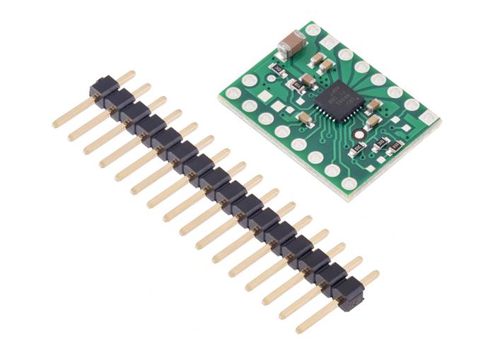
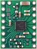
This product ships with all surface-mount components—including the DRV8434S driver IC—installed as shown in the product picture.
We also have a variety of other stepper motor driver options in this same form factor with different operating profiles and features.
Note: This driver needs to be enabled and configured through its SPI interface on power up, so your microcontroller must be capable of acting as an SPI master (either with an SPI peripheral or software SPI).
Some unipolar stepper motors (e.g. those with six or eight leads) can be controlled by this driver as bipolar stepper motors. For more information, please see the frequently asked questions. Unipolar motors with five leads cannot be used with this driver.

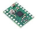
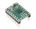
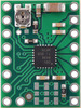
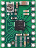
DRV8434S SPI Stepper Motor Driver Carrier, 2A Max. Current Limit (top view).
This version of the DRV8434S Stepper Motor Driver Carrier has a fixed 2 A maximum current limit. Header pins are included but not soldered (see item #3769 for a version of this carrier with header pins already installed). For a version that uses an on-board trimmer potentiometer to set the maximum current limit see item #3766.
The DRV8434S stepper motor driver carrier ships with one 1×16-pin breakaway 0.1″ male header. The headers can be soldered in for use with solderless breadboards or 0.1″ female connectors. You can also solder your motor leads and other connections directly to the board.
DRV8434S SPI Stepper Motor Driver Carrier, 2A Max. Current Limit with included headers. |
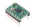
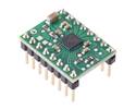
DRV8434S SPI Stepper Motor Driver Carrier, 2A Max. Current Limit with included header pins soldered. |

Typical wiring diagram for connecting a microcontroller to a DRV8434S stepper motor driver carrier.
The driver requires a motor supply voltage of 4.5 V to 48 V to be connected across VIN and GND. This supply should be capable of delivering the expected stepper motor current. Note that supply voltages below 6 V reduce the maximum current limit; see the Current limiting section for more details. The VSDO pin must also be supplied with the desired SPI logic voltage. The SPI interface on the DRV8434S is compatible with 1.8 V, 3.3 V, and 5 V systems.
Warning: We have observed that if the DRV8434S’s VSDO pin is left floating while VM is connected, VSDO can briefly output a pulse of voltage when nSLEEP changes state. Since our board pulls nSLEEP up to VSDO, this pulse can cause nSLEEP to briefly go high and then low again, causing more pulses and leading to an abnormal oscillating voltage on both pins.
To avoid this unwanted behaviour, we recommend that you avoid disconnecting VSDO and nSLEEP (or allowing them to float) while VM is present. (One way to be safe is to always disconnect motor power before disconnecting logic power.)
Four, six, and eight-wire stepper motors can be driven by the DRV8434S if they are properly connected; a FAQ answer explains the proper wirings in detail.
Warning: Connecting or disconnecting a stepper motor while the driver is powered can destroy the driver. (More generally, rewiring anything while it is powered is asking for trouble.)
Stepper motors typically have a step size specification (e.g. 1.8° or 200 steps per revolution), which applies to full steps. A microstepping driver such as the DRV8434S allows higher resolutions by allowing intermediate step locations, which are achieved by energizing the coils with intermediate current levels. For instance, driving a motor in quarter-step mode will give the 200-step-per-revolution motor 800 microsteps per revolution by using four different current levels.
The microstep resolution is configured through the SPI interface. For the microstep modes to function correctly, the current limit must be set low enough (see below) so that current limiting gets engaged. Otherwise, the intermediate current levels will not be correctly maintained, and the motor will skip microsteps.
While the DRV8434S allows control of a stepper motor through a simple step and direction interface, it must first be enabled and configured through its SPI interface after each power-up. This means that the controlling microcontroller must be capable of acting as an SPI master (either with an SPI peripheral or software SPI), and it must be connected to the SDI, SCLK, and SCS pins. While the SDO and FAULT pins are not required to use this driver, it is generally a good practice to use them to monitor for error conditions.
The rising edge of each pulse to the STEP input corresponds to one microstep of the stepper motor in the direction selected by the DIR pin. These inputs are both pulled down by default. If you just want rotation in a single direction, you can leave DIR disconnected. Stepping and direction can also both be controlled solely through SPI.
The chip has two different inputs for controlling its power states: SLEEP and ENABLE. For details about these power states, see the datasheet. SLEEP is connected to VSDO through a 10k pull-up resistor and ENABLE is internally pulled high by the chip. Since both pins are pulled up, they can both be left disconnected or dynamically controlled by connecting them to a digital output of an MCU.
The DRV8434S also features an open-drain FAULT output that drives low whenever the driver detects an under-voltage, over-current, open load, stall detection, or thermal shutdown fault. FAULT is pulled up to VSDO on the board, so no external pull-up resistor is needed.
Note: The open load, over-current protection, and over-temperature shutdown faults are latching by default and must be cleared with the CLR_FLT bit, a SLEEP reset pulse, or a power cycle. The latching behaviour of these faults can be reconfigured using the SPI interface.
To achieve high step rates, the motor supply is typically higher than would be permissible without active current limiting. For instance, a typical stepper motor might have a maximum current rating of 1 A with a 5 Ω coil resistance, which would indicate a maximum motor supply of 5 V. Using such a motor with 9 V would allow higher step rates, but the current must actively be limited to under 1 A to prevent damage to the motor.
The DRV8434S supports such active current limiting. This carrier has a fixed 2 A maximum current limit, and the TRQ_DAC bits can be used to scale that maximum current limit by a configurable percentage. There are 16 evenly spaced scale settings in increments of 125 mA. The motor current can be adjusted on the fly, and by decreasing the current when less torque is needed you can save power and reduce heat dissipation. We also carry a version of the DRV8434S with an on-board potentiometer for setting the maximum current limit which can then be scaled through SPI.
For input voltages below 6 V, the DRV8434S’s internally regulated logic voltage VDVDD linearly drops from 5 V with a 6 V input to around 4.35 V with a 4.5 V input. VDVDD supplies the resistor divider used to set the driver’s fixed 2 A current limit, so using supply voltages below 6 V will reduce the maximum current limit. With an input of 4.5 V, the maximum current limit would be 1.75 A, and the scale setting increments would be approximately 110 mA.
Note: The coil current can be very different from the power supply current, so if you want to measure the actual current through your stepper motor coils, the appropriate place to put your current meter is in series with one of your stepper motor coils. If the driver is in full-step 100% current or full-step 71% current modes, both coils will always be on and limited to 100% or 71% of the current limit setting respectively. If your driver is in one of the microstepping modes, the current through the coils will change with each step, ranging from 0% to 100% of the set limit. See the DRV8434S datasheet for more information.
The DRV8434S carrier has a maximum current rating of 2 A per coil, but the actual current you can deliver depends on how well you can keep the IC cool. The carrier’s printed circuit board is designed to draw heat out of the IC, but to supply more than approximately 1.2 A per coil, a heat sink or other cooling method is required.
This product can get hot enough to burn you long before the chip overheats. Take care when handling this product and other components connected to it.
Please note that measuring the current draw at the power supply will generally not provide an accurate measure of the coil current. Since the input voltage to the driver can be significantly higher than the coil voltage, the measured current on the power supply can be quite a bit lower than the coil current (the driver and coil basically act like a switching step-down power supply). Also, if the supply voltage is very high compared to what the motor needs to achieve the set current, the duty cycle will be very low, which also leads to significant differences between average and RMS currents. Additionally, please note that the coil current is a function of the set current limit, but it does not necessarily equal the current limit setting as the actual current through each coil changes with each microstep.
The DRV8434S driver can detect motor stall conditions or an end of travel by detecting back-EMF phase shift. An internal algorithm generates a measure of the phase shift called torque count which is independent of motor current, ambient temperature, and supply voltage. For a lightly loaded motor, the torque count will be a non-zero value. As the motor approaches a stall condition, torque count will approach zero. If the torque count falls below the stall threshold, the device will detect a stall. For details on using stall detection, please see the DRV8434S datasheet.
Please note that the DRV8434S’s stall detection has limitations, and how well it works will depend on the specifics of the application, including the choice of motor. In our tests, we have found it works better when the step signal is steady (e.g. provided by a microcontroller’s PWM timer output rather than software delays) and the speed is moderate. Here are some other considerations to be aware of:
We have written a DRV8434S library for Arduino that provides basic functions for configuring and operating the driver using an Arduino or Arduino-compatible controller. The library includes several example sketches.

Schematic diagram of the DRV8434S SPI Stepper Motor Driver Carrier.
This schematic is also available as a downloadable pdf (101k pdf).
| Size: | 0.6″ × 0.8″ |
|---|---|
| Weight: | 1.3 g1 |
| Minimum operating voltage: | 4.5 V2 |
|---|---|
| Maximum operating voltage: | 48 V3 |
| Continuous current per phase: | 1.2 A4 |
| Maximum current per phase: | 2 A5 |
| Minimum logic voltage: | 1.8 V6 |
| Maximum logic voltage: | 5.5 V7 |
| Microstep resolutions: | full with 100% current, full with 70% current, non-circular 1/2, 1/2, 1/4, 1/8, 1/16, 1/32, 1/64, 1/128, 1/256 |
| Current limit control: | fixed 2A max with SPI scaling |
| Reverse voltage protection?: | N |
| Header pins soldered?: | N |
| PCB dev codes: | md43b |
|---|---|
| Other PCB markings: | 0J13692 |
These DXF drawings show the locations of all of the holes on the DRV8434x Stepper Motor Driver Carriers.
This file contains 3D models (in the step file format) of the DRV8434x Stepper Motor Driver Carriers.
Texas Instruments product page for the DRV8434S, where you can find the latest datasheet and additional resources.
This is a library for Arduino that helps interface with a DRV8434S stepper motor driver. It uses the Arduino SPI library to communicate with the SPI interface (nSCS, SCLK, SDI, and SDO) of the DRV8434S.
Yes. To avoid damaging your stepper motor, you want to avoid exceeding the rated current, which is 600 mA in this instance. All of our stepper motor drivers let you limit the maximum current, so as long as you set the limit below the rated current, you will be within spec for your motor, even if the voltage exceeds the rated voltage. The voltage rating is just the voltage at which each coil draws the rated current, so the coils of your stepper motor will draw 600 mA at 3.9 V. By using a higher voltage along with active current limiting, the current is able to ramp up faster, which lets you achieve higher step rates than you could using the rated voltage.
If you do want to use a lower motor supply voltage for other reasons, consider using our DRV8834 or STSPIN-220 low-voltage stepper motor drivers.
Yes, you do! Setting the current limit on your stepper motor driver carrier is essential to making sure that it runs properly. An appropriate current limit also ensures that your motor is not allowed to draw more current than it or your driver can handle, since that is likely to damage one or both of them.
For the DRV8434A Stepper Motor Driver Carrier the current limit is set by adjusting the board’s potentiometer. We strongly recommend using a multimeter to measure the VREF voltage while setting the current limit so you can be sure you set it to an appropriate value (just turning the pot randomly until things seem to work is not a good approach). The following video has more details on setting the current limit:
Setting the current limit on the DRV8434S SPI Stepper Motor Driver Carrier, 2A Max. Current Limit is done through its SPI interface (this is very different from most of our other stepper motor driver carriers, which have their current limits set through their on-board potentiometers). The DRV8434S SPI Stepper Motor Driver Carrier, 2A Max defaults to its maximum possible current limit setting on start-up, which is much more current than the board can safely deliver, so you will need to set the current limit to an appropriate value for your stepper motor before enabling the driver outputs to prevent damage to the board. This is done by adjusting the TRQ_DAC bits in the CTRL1 register. The DRV8434S datasheet has more information on how to set the current limit through the SPI interface, and our Arduino library includes example sketches showing how to implement this in software.
For the DRV8434S SPI Stepper Motor Driver Carrier, Potentiometer for Max Current Limit, the current limit can be adjusted through both the onboard potentiometer and SPI. If the TRQ_DAC scaling factor at its left at its default of 100%, the potentiometer can be used alone to set the current limit, like with the DRV8434A. Otherwise, the TRQ_DAC value set through SPI is used to further scale the current limit set with the potentiometer.