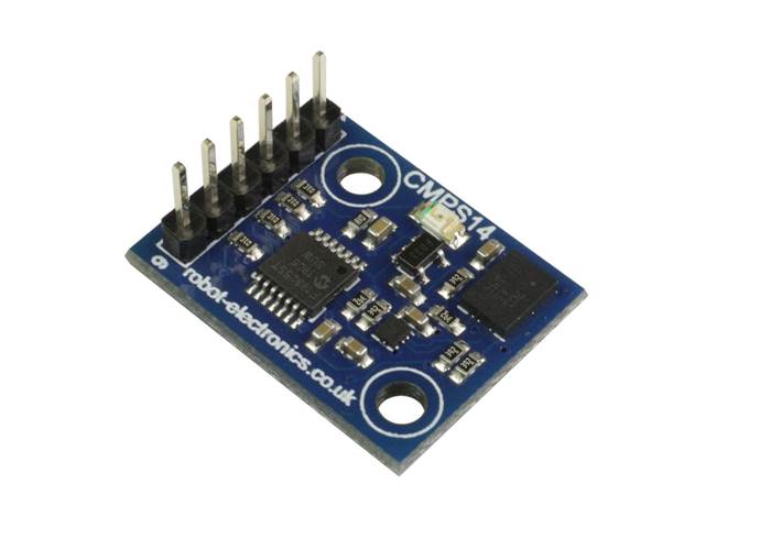
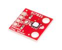
The CMPS14 is our 5th generation tilt compensated compass. Employing a 3-axis magnetometer, a 3-axis gyro and a 3-axis accelerometer. At the core of the module is the superb BNO080 running algorithms to remove the errors caused by tilting of the PCB. Powered from 3.3-5V @18mA the compass outputs the bearing reading via serial or I2C interface.
In stock in Australia
Shipping from $9.90
+lots more from our supplier in 7 days
Our Code: SEN-010088
The CMPS14 module is the 5th generation tilt compensated compass from Devantech. Employing a 3-axis magnetometer, 3 axis gyro and a 3-axis accelerometer and a powerful Kalman filter, the CMPS14 has been designed to remove the errors caused by tilting of the PCB.
The CMPS14 produces a result of 0-3599 representing 0-359.9 or 0 to 255. The output of the three sensors measuring x, y and z components of the magnetic field, together with the pitch and roll are used to calculate the bearing, each of these components are also made available in their raw form.
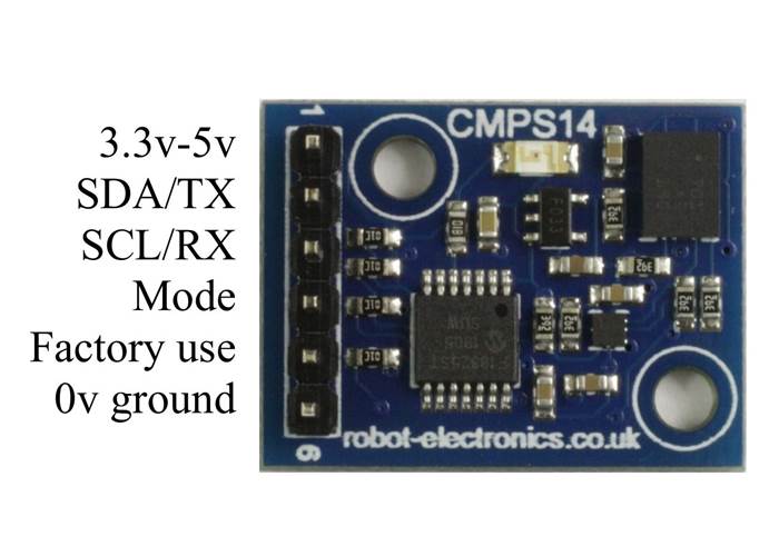
Examples of using the CMPS14 module with a wide range of popular controllers. The CMPS14 module requires a power supply at 3.3 - 5v and draws a nominal 18mA of current. There are two ways of getting the bearing from the module. A serial interface or an I2C interface
Full Technical Data
We also have a free design for a 3d printed tower here
Examples:
I2C bus tutor - general I2C guide
Arduino - I2C interface or a serial interface and displaying data via the serial monitor
ATMEGA32 - reading the result and displaying on a LCD03/LCD05
PIC18F4410 - reading the result and displaying on a LCD03/LCD05
PIC24FJ16GA002 - reading the result and displaying on a LCD03/LCD05
Picaxe18x - I2C communication example
Raspberry Pi - using I2C communication
Power - 3.3v-5v 18mA Typ.
Resolution - 0.1 Degree
Accuracy - Better than 1%. after calibration
Signal levels - 3.3v, 5v tolerant
I2C mode - up to 400khz
Serial mode - 9600, 19200, 38400 baud
Full Technical Data