The Tic T834 USB Multi-Interface Stepper Motor Controller makes basic control of a stepper motor easy, with quick configuration over USB using our free software.
In stock in Australia
Shipping from $9.90
+17 more from our supplier in 7-10 days
Our Code: SKU-004347
Supplier Link: [Pololu MPN:3132]
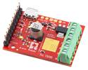
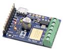
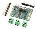
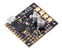
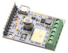
The Tic T834 USB Multi-Interface Stepper Motor Controller makes basic control of a stepper motor easy, with quick configuration over USB using our free software. The controller supports six control interfaces: USB, TTL serial, I²C, analog voltage (potentiometer), quadrature encoder, and hobby radio control (RC). This version incorporates a TI DRV8834 driver and ships with soldered header pins and terminal blocks. It can operate from 2.5 V to 10.8 V and can deliver up to approximately 1.5 A per phase without a heat sink or forced air flow (or 2 A max with sufficient additional cooling).
The Tic family of stepper motor controllers makes it easy to add basic control of a bipolar stepper motor to a variety of projects. These versatile, general-purpose modules support six different control interfaces: USB for direct connection to a computer, TTL serial and I²C for use with a microcontroller, RC hobby servo pulses for use in an RC system, analog voltages for use with a potentiometer or analog joystick, and quadrature encoder for use with a rotary encoder dial. They also offer many settings that can be configured using our free configuration utility (for Windows, Linux, and macOS). This software simplifies initial setup of the device and allows for in-system testing and monitoring of the controller via USB (a micro-B USB cable is required to connect the Tic to a computer).
The table below lists the members of the Tic family and shows the key differences among them.
 Tic T500 |
 Tic T834 |
 Tic T825 |
 Tic T249 |
 Tic 36v4 |
|
|---|---|---|---|---|---|
| Operating voltage range: | 4.5 V to 35 V(1) | 2.5 V to 10.8 V | 8.5 V to 45 V(1) | 10 V to 47 V(1) | 8 V to 50 V(1) |
| Max continuous current per phase (no additional cooling): |
1.5 A | 1.5 A | 1.5 A | 1.8 A | 4 A |
| Peak current per phase (additional cooling required): |
2.5 A | 2 A | 2.5 A | 4.5 A | 6 A |
| Microstep resolutions: | full half 1/4 1/8 |
full half 1/4 1/8 1/16 1/32 |
full half 1/4 1/8 1/16 1/32 |
full half 1/4 1/8 1/16 1/32 |
full half 1/4 1/8 1/16 1/32 1/64 1/128 1/256 |
| Automatic decay selection: |  |
|
|
||
| Automatic gain control (AGC): | |
||||
| Driver IC: | MP6500 | DRV8834 | DRV8825 | TB67S249FTG | discrete MOSFETs |
| Price (connectors not soldered): | $32.95 | $42.95 | $42.95 | $52.95 | $62.95 |
| Price (connectors soldered): | $34.95 | $44.95 | $44.95 | $54.95 | $64.95 |
1 See product pages and user’s guide for operating voltage limitations.
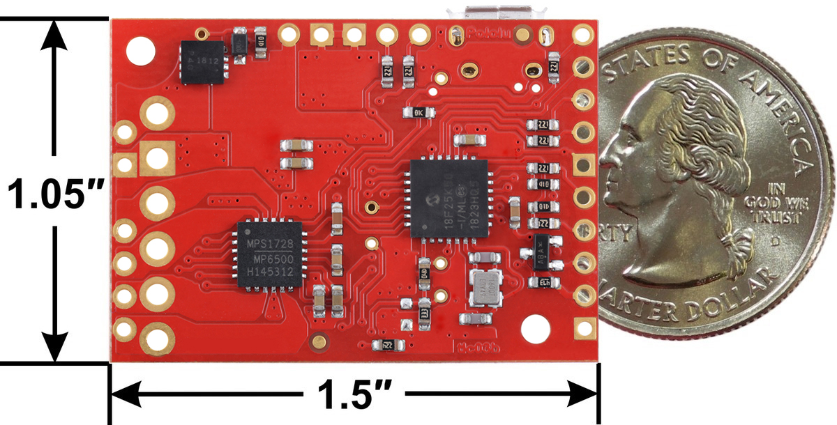 |
Tic T500 USB Multi-Interface Stepper Motor Controller, bottom view with dimensions. |
|---|
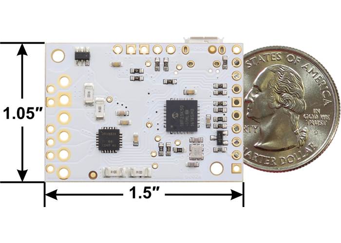
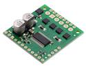
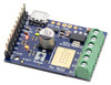
Tic T834 USB Multi-Interface Stepper Motor Controller, bottom view with dimensions.
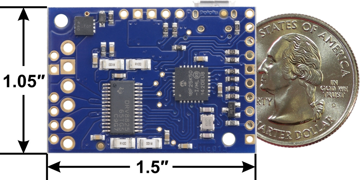 |
Tic T825 USB Multi-Interface Stepper Motor Controller, bottom view with dimensions. |
|---|
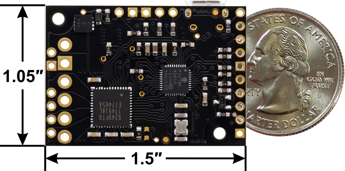 |
Tic T249 USB Multi-Interface Stepper Motor Controller, bottom view with dimensions. |
|---|
 |
Tic 36v4 USB Multi-Interface High-Power Stepper Motor Controller, bottom view with dimensions. |
|---|
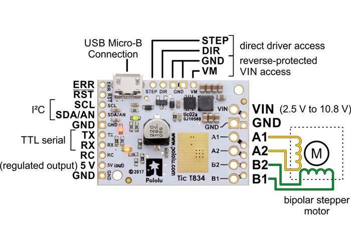
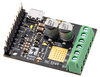
Basic pinout diagram of the Tic T834 USB Multi-Interface Stepper Motor Controller.
The Tic T834 is based on the DRV8834 IC from Texas Instruments. It can operate from 2.5 V to 10.8 V and can deliver up to approximately 1.5 A continuous per phase without a heat sink or forced air flow (the peak current per phase is 2 A). This version is sold with connectors soldered so no soldering is necessary to use it.

Tic T834 USB Multi-Interface Stepper Motor Controller (Connectors Soldered).
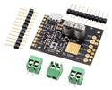
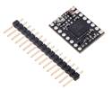
A version is also available with header pins and terminal blocks included but not soldered.
| Size: | 1.50″ × 1.05″ × 0.47″ |
|---|---|
| Weight: | 8.4 g |
| Model: | Tic T834 |
|---|---|
| Motor driver: | DRV8834 |
| Control interface: |
USB; non-inverted TTL serial; I²C; RC servo pulses; analogue voltage; quadrature encoder |
| Minimum operating voltage: | 2.5 V |
| Maximum operating voltage: | 10.8 V |
| Continuous current per phase: | 1.5 A1 |
| Maximum current per phase: | 2 A2 |
| Maximum step rate: | 50000 PPS |
| Microstep resolutions: | full, 1/2, 1/4, 1/8, 1/16, and 1/32 |
| Reverse voltage protection?: | Y |
| Connectors soldered?: | Y |
| PCB dev codes: | tic02a |
|---|---|
| Other PCB markings: | 0J10607 |
User’s manual for the Pololu Tic USB Stepper Motor Controller.
This file contains 3D models (in the step file format) of all the Tic USB Multi-Interface Stepper Motor Controllers.
This file contains DXF drawings that show the locations of the holes on all of the different Tic PCBs.
The official specification for the I²C-bus, which is maintained by NXP.
Getting up and running with your Tic stepper motor controller from Pololu is easy. This video will guide you through the basic steps to connect your Tic to its software and control a stepper motor from your computer.
This repository contains the source code of the Pololu Tic Command-line Utility (ticcmd) and the Pololu Tic Control Center (ticgui). It also has drivers for Windows and build instructions.
This is a library for the Arduino IDE that helps interface with a Tic Stepper Motor Controller using serial or I²C.
Yes. To avoid damaging your stepper motor, you want to avoid exceeding the rated current, which is 600 mA in this instance. All of our Tic stepper motor controllers have configurable current limiting, so you can set a limit that is appropriate for your stepper motor. As long as you set the limit below the rated current, you will be within spec for your motor, even if the voltage exceeds the rated voltage. The voltage rating is just the voltage at which each coil draws the rated current, so the coils of your stepper motor will draw 600 mA at 3.9 V. By using a higher voltage along with active current limiting, the current is able to ramp up faster, which lets you achieve higher step rates than you could using the rated voltage.
If you do want to use a lower motor supply voltage for other reasons, consider using the Tic T834, which operates from 2.5 V to 10.8 V, or the Tic T500, which operates from 4.5 V to 35 V.