The Jrk 21v3 motor controller is a highly configurable brushed DC motor controller that supports four interface modes: USB, logic-level serial, analogue voltage, and hobby radio control (RC).
Special Order
Shipping from $9.90
+15 more from our supplier in 7-10 days
Our Code: SKU-002570
Supplier Link: [Pololu MPN:1394]
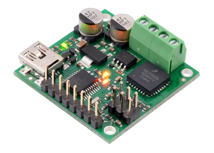
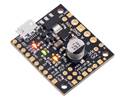
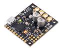
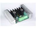
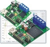
The Jrk 21v3 motor controller is a highly configurable brushed DC motor controller that supports four interface modes: USB, logic-level serial, analog voltage, and hobby radio control (RC). The controller can be used with feedback for closed-loop speed or position control, or it can be used without feedback as an open-loop speed control. The continuous output current is approximately 3 A in the recommended operating range of 8 V to 28 V, with derated performance down to 5 V and transient protection to 40 V. This version ships with connectors installed as shown (no soldering required).
Not recommended for new designs: We strongly recommend our newer and better (and smaller) Jrk G2 21v3 USB Motor Controller with Feedback over this controller, as it offers increased power and many other improvements at a lower price. We are continuing to offer the original Jrk 21v3 for now as a legacy product for those with systems designed specifically for this controller.

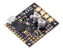
Pololu Jrk 21v3 USB motor controller with dimensions.
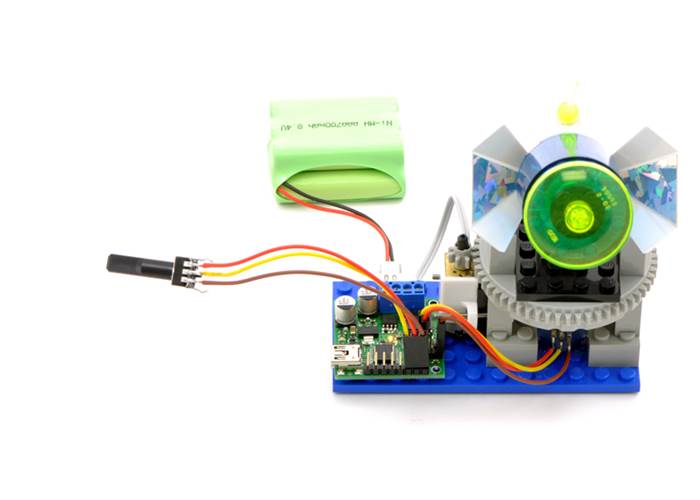
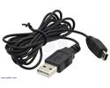
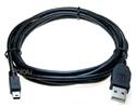
The Jrk 21v3 is a versatile, general-purpose motor controller that supports a variety of interfaces, including USB. The broad operating range from 5 V to 28 V and continuous output current of 3 A (5 A peak) allow this board to control most small DC brushed motors. Analogue voltage and tachometer (frequency) feedback options allow quick implementation of closed-loop servo systems, and a free configuration utility (for Windows) allows easy calibration and configuration through the USB port. A USB A to mini-B cable (not included) is required to connect this controller to a computer.
Key improvements over competing products and earlier Pololu motor controllers with feedback include:
The table below lists the members of the Jrk family, including the original (green) and newer G2 (black) versions, and shows the key differences among them.
 Jrk 21v3 |
 Jrk G2 21v3 |
 Jrk G2 18v19 |
 Jrk G2 24v13 |
 Jrk G2 18v27 |
 Jrk G2 24v21 |
|
|---|---|---|---|---|---|---|
| Recommended max operating voltage: |
28 V(1) | 28 V(1) | 24 V(2) | 34 V(3) | 24 V(2) | 34 V(3) |
| Max nominal battery voltage: |
24 V | 24 V | 18 V | 28 V | 18 V | 28 V |
| Max continuous current (no additional cooling): |
2.5 A* | 2.6 A | 19 A | 13 A | 27 A | 21 A |
| USB, TTL serial, Analogue, RC control: |
 |
|
|
|
|
|
| I²C control: | |
|
|
|
|
|
| Hardware current limiting: | |
|
|
|
||
| Dimensions: | 1.35″ × 1.35″ | 1.0″ × 1.2″ | 1.4″ × 1.2″ | 1.7″ × 1.2″ | ||
| Price: | $74.95 | $54.95 | $109.95 | $109.95 | $149.95 | $149.95 |
| 1 Transient operation (< 500 ms) up to 40 V. 2 30 V absolute max. 3 40 V absolute max. * Reduced from “3 A” based on newer, more stringent tests. The value now is directly comparable to the rating for the newer G2 21v3. |
||||||

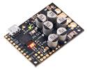
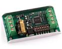
Pololu Jrk 21v3 USB motor controller with feedback, labeled top view.

The Input tab of the Jrk Configuration Utility

The Jrk plot window, showing all variables simultaneously.
| Motor channels: | 1 |
|---|---|
| Operating voltage: | 5 V to 28 V |
| Continuous output current: | 3 A |
| Peak output current: | 5 A |
| Auto-detect baud rate range: | 300 bps to 115,200 bps |
| Available fixed baud rates: | 300 bps to 115,200 bps |
| Available PWM frequencies: | 20 kHz, 5 kHz |
| Reverse voltage protection?: | Yes |
| USB connector style: | USB Mini-B |
The Jrk 21v3 is the smaller of two Jrk motor controllers. For a higher-power version, see the Jrk 12v12.
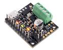
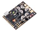
Pololu Jrk 21v3 USB motor controller with included hardware soldered in (fully assembled). |
|
The Jrk 21v3 is available in two versions: “fully assembled” with terminal blocks and 0.1″ male header pins pre-installed (left picture above), and connector-free (right picture above). The connector-free version includes a straight 0.1″ breakaway male header strip and two 3.5mm, 2-pin terminal blocks, but these parts are not soldered to the board, which allows for custom installations.
The three mounting holes are intended for use with #2 screws (not included).
|
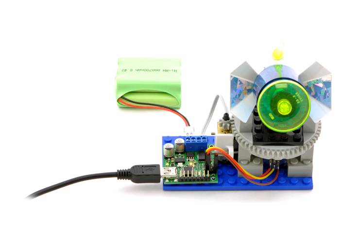
USB control. |
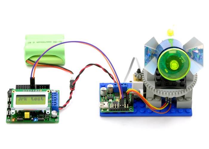
TTL serial control. |
|
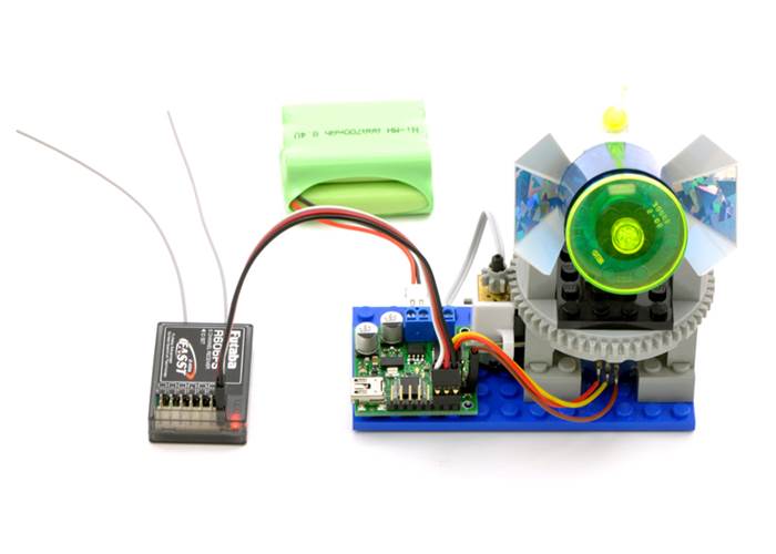
RC / pulse width control. |
Analog control. |
| Size: | 1.35" x 1.35" x 0.5" |
|---|---|
| Weight: | 0.23 oz |
| Motor driver: | MC33926 |
|---|---|
| Motor channels: | 1 |
| Control interface: |
USB; non-inverted TTL serial; RC servo pulses; analogue voltage1 |
| Minimum operating voltage: | 5 V |
| Maximum operating voltage: | 28 V |
| Continuous output current per channel: | 3 A |
| Peak output current per channel: | 5 A |
| Current sense: | 0.5 V/A2 |
| Maximum PWM frequency: | 20 kHz |
| Minimum logic voltage: | 4 V3 |
| Maximum logic voltage: | 5 V |
| Reverse voltage protection?: | Y |
| Partial kit?: | N |
The user’s guide for the Jrk 21v3 USB Motor Controller and the Jrk 12v12 USB Motor Controller.
The Pololu USB SDK contains example code for making your own applications that use native USB to control the Jrk Motor Controller, Maestro Servo Controller, Simple Motor Controller, or USB AVR Programmer.

An application note about using AutoHotkey for Windows to control Pololu USB products.
This ZIP archive contains the installation files for the Jrk Configuration Utility, the Jrk command-line utility (JrkCmd), and the Jrk drivers for Microsoft Windows.
Use a Jrk 21v3 to precisely control our Concentric LD series linear actuators with feedback. Instructions for using this file can be found on the linear actuator product pages.
This DXF drawing shows the locations of all of the board’s holes.
A spooky animatronic skeleton using the Jrk USB Motor Controller. See the final result. By Mark Goodson, October 2009.
A replica of the famous Star Wars droid R2D2 that uses the Jrk USB Motor Controller for position control. See the video which shows the Jrk Configuration Utility in action, or read the blog post which has more information. By ggpipe, February 2010.
The Microsoft .NET Framework version 3.5 is required for many Pololu configuration, control, and utility programs under Windows. Most computers will have this installed already or can automatically install it over the internet, but you can also get .NET 3.5 directly from Microsoft at this link. If you are installing on a computer without internet access, make sure to get the Full Redistributable Package.