Stepper Motor: Bipolar, 200 Steps/Rev, 35×28mm, 10V, 0.5 A/Phase

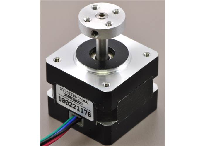
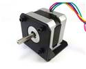
This NEMA 14-size hybrid bipolar stepping motor has a 1.8° step angle (200 steps/revolution). Each phase draws 500 mA at 10 V, allowing for a holding torque of 1 kg-cm (14 oz-in).

AUD$ 36.95

Special Order  

Shipping from $7.90

+316 more from our supplier in 7-10 days

Our Code: SKU-002541

Supplier Link: [Pololu MPN:1208]


Description

Overview

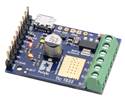
This hybrid bipolar stepping motor has a 1.8° step angle (200 steps/revolution). Each phase draws 500 mA at 10 V, allowing for a holding torque of 1 kg-cm (14 oz-in). The motor has four colour-coded wires terminated with bare leads: black and green connect to one coil; red and blue connect to the other. It can be controlled by a pair of suitable H-bridges (one for each coil), but we recommend using a bipolar stepper motor driver.

5mm Pololu universal aluminum mounting hub on a stepper motor with a 5mm-diameter output shaft

NEMA 14 stepper motor (item #1207) mounted with a Pololu stamped aluminum L-bracket for NEMA 14 stepper motors

Bipolar stepper motor wires are terminated with bare leads

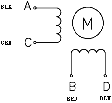
Bipolar stepper motor wiring diagram.

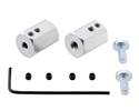
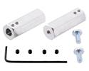
Our 5 mm universal mounting hub can be used to mount objects on the stepper motor’s 5 mm-diameter output shaft, and our NEMA 14 aluminium bracket offers a variety of options for mounting this stepper motor in your project.

Specifications

  • Size: 35 mm square × 28 mm, not including the shaft (NEMA 14)
  • Weight: 140 g (5 oz)
  • Shaft diameter: 5 mm “D”
  • Steps per revolution: 200
  • Current rating: 500 mA per coil
  • Voltage rating: 10 V
  • Resistance: 20 Ω per coil
  • Holding torque: 1 kg-cm (14 oz-in)
  • Inductance: 13.5 mH per coil
  • Lead length: 30 cm (12″)
  • Output shaft supported by two ball bearings

More specifications are available in the datasheet (185k pdf).

Dimensions

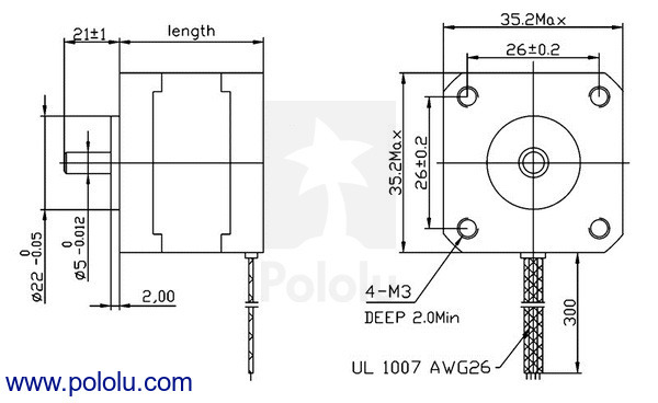
The following diagram shows the stepper motor dimensions in mm. The dimension labelled “length” is 28 mm. The output D-shaft has a length of 21 mm and a 5 mm diameter with a section that is flattened by 0.5 mm. This shaft works with our 5 mm universal mounting hub.

The inside of a bipolar stepper motor

Stepper Motor Applications

Stepper motors are generally used in a variety of applications where precise position control is desirable and the cost or complexity of a feedback control system is unwarranted. Here are a few applications where stepper motors are often found:

  • Printers
  • CNC machines
  • 3D printer/prototyping machines (e.g. RepRap)
  • Laser cutters
  • Pick and place machines
  • Linear actuators
  • Hard drives

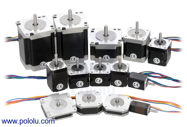
Pololu’s assortment of stepper motors.

Note: This stepper motor is SOYO part number SY35ST28-0504A.


Specifications

Dimensions

Size: 35 mm square × 28 mm1
NEMA size: 14
Weight: 140 g
Shaft diameter: 5 mm

General specifications

Shaft type: 5 mm "D"
Steps per revolution: 200
Current rating: 500 mA2
Voltage rating: 10 V
Holding torque: 14 oz·in
Resistance: 20 Ohm2
Inductance per phase: 13.5 mH
Number of leads: 4
Lead length: 30 cm

Notes:

1
Not including the shaft.
2
Per coil.

Resources

File downloads

SY35ST28-0504A stepper motor datasheet (185k pdf)

FAQs

I want to control a 3.9 V, 600 mA bipolar stepper motor like this, but your A4988 stepper motor driver carrier has a minimum operating voltage of 8 V. Can I use this driver without damaging the stepper motor?

Yes. To avoid damaging your stepper motor, you want to avoid exceeding the rated current, which is 600 mA in this instance. The A4988 stepper motor drivers let you limit the maximum current, so as long as you set the limit below the rated current, you will be within spec for your motor, even if the voltage exceeds the rated voltage. The voltage rating is just the voltage at which each coil draws the rated current, so the coils of your stepper motor will draw 600 mA at 3.9 V. By using a higher voltage along with active current limiting, the current is able to ramp up faster, which lets you achieve higher step rates than you could using the rated voltage.

If you do want to use a lower motor supply voltage (under 8 V) for other reasons, consider using our DRV8834 low-voltage stepper motor driver carrier.

How do I connect my stepper motor to the A4983 or A4988 stepper motor driver carrier?

The answer to this question depends on the type of stepper motor you have. When working with stepper motors, you will typically encounter two types: unipolar stepper motors and bipolar stepper motors. Unipolar motors have two windings per phase, allowing the magnetic field to be reversed without having to reverse the direction of current in a coil, which makes unipolar motors easier to control than bipolar stepper motors. The drawback is that only half of the phase is carrying current at any given time, which decreases the torque you can get out of the stepper motor. However, if you have the appropriate control circuitry, you can increase the stepper motor torque by using the unipolar stepper motor as a bipolar stepper motor (note: this is only possible with 6- or 8-lead unipolar stepper motors, not with 5-lead unipolar stepper motors). Unipolar stepper motors typically have five, six, or eight leads.

Bipolar steppers have a single coil per phase and require more complicated control circuitry (typically an H-bridge for each phase). The A4983 and A4988 have the circuitry necessary to control a bipolar stepper motor. Bipolar stepper motors typically have four leads, two for each coil.

Two-phase bipolar stepper motor with four leads.

The above diagram shows a standard bipolar stepper motor. To control this with the A4983 or A4988, connect stepper lead A to board output 1A, stepper lead C to board output 1B, stepper lead B to board output 2A, and stepper lead D to board output 2B. See the A4983/A4988 datasheet for more information.

If you have a six-lead unipolar stepper motor as shown in the diagram below:

Two-phase unipolar stepper motor with six leads.

you can connect it to the A4983 or A4988 as a bipolar stepper motor by making the bipolar connections described in the section above and leaving stepper leads A’ and B’ disconnected. These leads are centre taps to the two coils and are not used for bipolar operation.

If you have an eight-lead unipolar stepper motor as shown in the diagram below:

Two-phase unipolar stepper motor with eight leads.

you have several connection options. An eight-lead unipolar stepper motor has two coils per phase, and it gives you access to all of the coil leads (in a six-lead unipolar motor, lead A’ is internally connected to C’ and lead B’ is internally connected to D’). When operating this as a bipolar stepper, you have the option of using the two coils for each phase in parallel or in series. When using them in parallel, you decrease coil inductance, which can lead to increased performance if you have the ability to deliver more current. However, since the A4983 and A4988 actively limit the output current per phase, you will only get half the phase current flowing through each of the two parallel coils. When using them in series, it’s like having a single coil per phase (like in four-lead bipolar steppers or six-lead unipolar steppers used as bipolar steppers). We recommend you use a series connection.

To connect the phase coils in parallel, connect stepper leads A and C’ to board output 1A, stepper leads A’ and C to board output 1B, stepper leads B and D’ to board output 2A, and stepper leads B’ and D to board output 2B.

To connect the phase coils in series, connect stepper lead A’ to C’ and stepper lead B’ to D’. Stepper leads A, C, B, and D should be connected to the stepper motor driver as normal for a bipolar stepper motor (see the bipolar stepper connections above).

Related Products