This module is a carrier board for TI’s ISO6541F general purpose functional isolator, which enables four channels of galvanically isolated digital communication between two devices at up to 50 Mbps per channel.
Special Order
Shipping from $4.90
+79 more from our supplier in 7-10 days
Our Code: SKU-011388
Supplier Link: [Pololu MPN:5743]
This module is a carrier board for TI’s ISO6541F general purpose functional isolator, which enables four channels of galvanically isolated digital communication between two devices at up to 50 Mbps per channel. It provides three forward channels and one reverse channel, and they default to low in the event of input power or signal loss.
These modules are carrier boards or breakout boards for the ISO654x general purpose functional isolators from Texas Instruments; we therefore recommend referring to the ISO654x datasheet for detailed specifications. The ISO654x features four digital channels that enable communication between two galvanically (electrically) isolated devices at up to 50 Mbps per channel. This isolation means that current cannot flow from one side to the other, and incorrect connections or bad voltages on one side cannot propagate through to damage the device on the other side. It also means the logic voltage can be at different levels on the two sides, allowing these carrier boards to function as level shifters.
The six IC versions feature different combinations of channel directions and default output behaviour as shown in the table below:
| Pololu Item # |
IC part number |
Default output |
Channels | Max data rate |
Working voltage 1 |
Min PCB Creepage 2 |
Size | Price | |
|---|---|---|---|---|---|---|---|---|---|
 ISO654x carrier |
#5740 | ISO6540 | high | 4 forward, 0 reverse |
50 Mbps | 400 VRMS | 5.3 mm | 0.6″×0.7″ | $2.75 |
| #5741 | ISO6540F | low | |||||||
| #5742 | ISO6541 | high | 3 forward, 1 reverse |
||||||
| #5743 | ISO6541F | low | |||||||
| #5744 | ISO6542 | high | 2 forward, 2 reverse |
||||||
| #5745 | ISO6542F | low | |||||||
| Note 1: IC component functional isolation rating per manufacturer datasheet. | |||||||||
| Note 2: Minimum creepage along PCB surface based on layout design only. Other creepage distances, e.g. along the body of the component, may be lower. | |||||||||

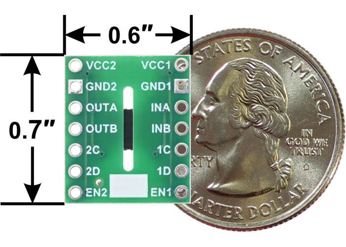
Pinouts of the ISO654x 4-Channel Digital Isolator Carrier series.
This is the version features the ISO6541F, which has three forward channels and one reverse channel and defaults to low in the event of input power or signal loss. It can be differentiated from the other versions by the “6541F” marking on the IC, and there is also a blank white rectangle on the bottom silkscreen for adding your own distinguishing marks.
Pinout of the ISO6541/ISO6541F 4-Channel Digital Isolator Carrier. |
ISO654x 4-Channel Digital Isolator Carrier, bottom view with dimensions and a US quarter for size reference. |
| PIN | Type | Description |
|---|---|---|
| VCC1 | Side 1 power supply. Valid ranges: 1.71 V to 1.89 V or 2.25 V to 5.5 V. Note: Side 1 channel output states are undetermined for 1.05 V < VCC1 < 1.71 V and 1.89 V < VCC1 < 2.25 V . | |
| GND1 | Ground connection for VCC1. | |
| VCC2 | Side 2 power supply. Valid ranges: 1.71 V to 1.89 V or 2.25 V to 5.5 V. Note: Side 2 channel output states are undetermined for 1.05 V < VCC2 < 1.71 V and 1.89 V < VCC2 < 2.25 V . | |
| GND2 | Ground connection for VCC2. | |
| INA | input | Input, channel A |
| INB | input | Input, channel B |
| INC | input | Input, channel C |
| IND | input | Input, channel D |
| OUTA | output | Output, channel A |
| OUTB | output | Output, channel B |
| OUTC | output | Output, channel C |
| OUTD | output | Output, channel D |
| EN1 | input | Side 1 output enable. Output pins on side 1 are enabled when EN1 is high or open and in a high-impedance state when EN1 is low |
| EN2 | input | Side 2 output enable. Output pins on side 2 are enabled when EN2 is high or open and in a high-impedance state when EN2 is low |
Each side must be powered separately across its respective VCCx and GNDx pins, and the voltages on the two sides can be at different levels. The two sides are galvanically isolated (GND1 is NOT connected to GND2).

Schematic diagram of the ISO654x 4-Channel Digital Isolator Carrier.
The ISO654x provides functional isolation with a manufacturer-rated working voltage of 400 VRMS. The IC package has a clearance and creepage of >3.7 mm, and our carrier PCB has a routed slot under the IC that increases the PCB creepage to 5.3 mm. A rough rule of thumb is that uncontaminated FR4 PCBs should have roughly 1 mm of creepage per 100 VRMS of isolation. Please note that these carrier boards are not certified to any particular safety standard.
| Size: | 0.6″ × 0.7″ × 0.11″ |
|---|---|
| Weight: | 0.5 g |
| Maximum data rate: | 50 Mbps |
|---|---|
| Minimum operating voltage: | 1.71 V1 |
| Maximum operating voltage: | 5.5 V1 |
| Channel directions: | 3 forward, 1 reverse |
| Default output: | low |
| Working isolation voltage: | 400 VRMS |
| Isolated power transfer?: | N |
| IC part number: | ISO6541F |
| PCB dev codes: | iso05a |
|---|---|
| Other PCB markings: | 0J16075, blank white box |
This DXF drawing shows the locations of all of the board’s holes.