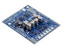
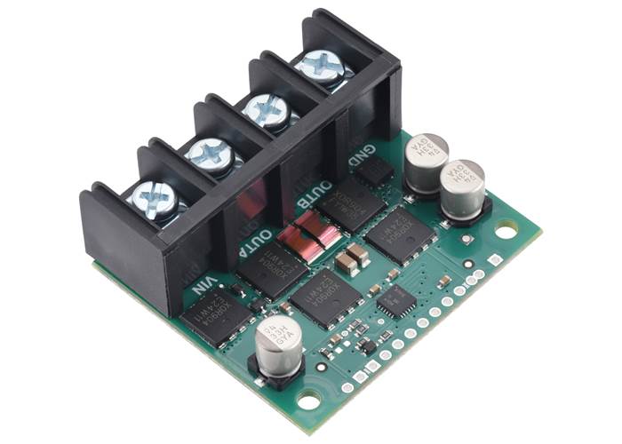
This discrete MOSFET H-bridge motor driver enables bidirectional control of one high-power brushed DC motor. The 1.9″ × 1.7″ board supports a wide 6.5 V to 40 V voltage range and is efficient enough to deliver up to around 30 A continuous without a heat sink.
Special Order
Shipping from $9.90
+76 more from our supplier in 7-10 days
Our Code: SKU-011340
Supplier Link: [Pololu MPN:5692]
This discrete MOSFET H-bridge motor driver enables bidirectional control of one high-power brushed DC motor. The 1.9″ × 1.7″ board supports a wide 6.5 V to 40 V voltage range and is efficient enough to deliver up to around 30 A continuous without a heat sink. Additional features include reverse-voltage protection, basic current limiting, and an on-board current sensor that provides a direct measurement of the motor current.
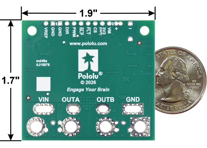
Pololu G2 High-Power Motor Driver 24v30 CS, bottom view with dimensions and a US quarter for size reference.
The Pololu G2 high-power motor driver is a discrete MOSFET H-bridge designed to drive large brushed DC motors. The H-bridge is made up of one N-channel MOSFET per leg; the rest of the board contains the circuitry to take user inputs and control the MOSFETs. The absolute maximum voltage for this motor driver is 40 V, and higher voltages can permanently destroy the motor driver. Under normal operating conditions, ripple voltage on the supply line can raise the maximum voltage to more than the average or intended voltage, so a safe maximum voltage is approximately 34 V.
Note: Battery voltages can be much higher than nominal voltages when they are charged, so the maximum nominal battery voltage we recommend is 28 V unless appropriate measures are taken to limit the peak voltage.
The versatility of this driver makes it suitable for a large range of currents and voltages, with the ability to deliver up to around 30 A of continuous current without heat sinking or forced airflow. The module offers a simple interface that requires as few as two I/O lines while still allowing for your choice of sign-magnitude or locked-antiphase operation. An on-board current sensor gives a direct measurement of the motor current, and the driver can limit the motor current to a configurable threshold. The power supply inputs feature reverse-voltage protection, while integrated detection of various fault conditions helps protect against other common causes of catastrophic failure; however, please note that the board does not include over-temperature protection.
The following table provides a general comparison of the G2 and H2 drivers, which are available in six single-channel versions and eight dual-channel versions. Four of the dual-channel drivers have the form factor of an Arduino shield, but they can also be used with other controllers as general-purpose motor drivers. The other four dual-channel drivers are in the form factor of a Raspberry Pi HAT and compatible Raspberry Pi boards (Model B+ or newer). The single-channel G2 drivers all have the same form factor except for the highest-power 24v30, which is larger to accommodate the much larger MOSFETs. We also have a higher-voltage, single-channel H2 high-power motor driver with the same form factor as the single-channel G2 drivers, but the control interface and some aspects of the operation are different.
| G2 and H2 High-Power Motor Drivers | ||||||||||
|---|---|---|---|---|---|---|---|---|---|---|
 G2 18v17 |
 G2 18v25 |
 G2 24v13 |
 G2 24v21 |
 G2 24v30 CS |
 H2 36v11 CS |
 G2 18v18 |
 G2 18v22 |
 G2 24v14 |
 G2 24v18 |
|
| Motor channels | single (1) | dual (2) | ||||||||
| Min. operating voltage | 6.5 V | 5 V | 6.5 V | |||||||
| Absolute max. input voltage | 30 V | 40 V | 60 V | 30 V | 40 V | |||||
| Max. nominal battery voltage | 18 V | 28 V | 36 V | 18 V | 28 V | |||||
| Max. continuous current(1) | 17 A | 25 A | 13 A | 21 A | 30 A | 11 A | 18 A | 22 A | 14 A | 18 A |
| Current sense feedback | 20 mV/A | 10 mV/A | 40 mV/A | 20 mV/A | 13.2 mV/A | 60 mV/A(2) | 20 mV/A | 10 mV/A | 20 mV/A | 20 mV/A |
| Direct motor current measurement |
— | — | — | — | — | — | — | — | ||
| Default current limit(3) | 40 A | 60 A | 30 A | 50 A | 100 A | n/a | 50 A | 60 A | 40 A | 50 A |
| Size | 1.3″ × 0.8″ | 1.7″ × 1.9″ | 1.3″ × 0.8″ | 2.56″ × 2.02″ | ||||||
| Shield version available? | — | — | — | — | — | — | Yes | Yes | Yes | Yes |
| Raspberry Pi expansion version available? |
— | — | — | — | — | — | Yes | Yes | Yes | Yes |
| 1-piece price | $44.95 | $56.95 | $44.95 | $56.95 | $74.95 | $56.95 | $74.95 | $104.95 | $79.95 | $104.95 |
| Note 1: Per motor channel, at room temperature and without heat sinking or forced air flow. | ||||||||||
| Note 2: When VCC = 5 V; sensitivity is proportional to VCC. | ||||||||||
| Note 3: Can be adjusted lower. | ||||||||||
|
Pololu G2 High-Power Motor Driver 24v30 CS. (1) |
|
|
|
|
Note: As an alternative to these motor drivers, our Simple Motor Controllers have similar power characteristics and offer high-level interfaces (e.g. USB, RC hobby servo pulses, analogue voltages, and TTL serial commands) that make them easier to use for some applications.

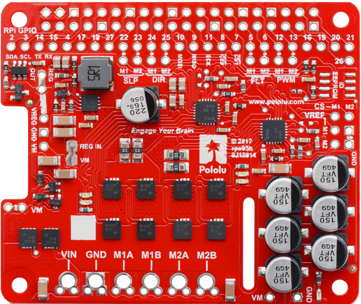
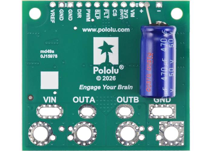
Pinout of the Pololu G2 High-Power Motor Driver 24v30 CS.
| PIN | Default State | Description |
|---|---|---|
| VIN | This is the main 6.5 V to 40 V (absolute max) motor power supply connection. | |
| GND | Ground connection for logic and motor power supplies. | |
| OUTA | Motor output pin A (connects to one terminal of a DC motor). | |
| OUTB | Motor output pin B (connects to the other terminal of a DC motor). | |
| VM | This pin gives you access to the motor power supply after reverse-voltage protection. It can be used to supply reverse-protected power to other components in the system, but it should not be used for high currents. This pin should only be used as an output. | |
| +, − | These through-holes are intended for a power supply capacitor (they are connected to VM and GND, respectively). | |
| 3V3 (out) | This regulated 3.3 V output provides a few milliamps, which can be useful as a reference or for powering small external circuits. This output should not be connected to other external power supply lines. It is disabled when the driver is in sleep mode. Be careful not to accidentally short this pin to the neighbouring VM pin while power is being supplied as doing so will instantly destroy the board! | |
| DIR | LOW | Direction input: when DIR is high, current will flow from OUTA to OUTB; when it is low, current will flow from OUTB to OUTA. |
| PWM | LOW | Pulse width modulation input: a PWM signal on this pin corresponds to a PWM output on the motor outputs. |
| SLP | HIGH | Inverted sleep input: This pin is pulled high by the driver board, enabling the driver by default; drive SLP low to put the motor driver into a low-power sleep mode. |
| FLT | Fault indicator: This open-drain output is driven low when a fault has occurred. See below for details. To use this output, externally pull this pin up to your system’s logic voltage. | |
| CS | Current sensor output: This pin outputs a voltage proportional to the motor current. See below for details. | |
| VREF | Reference voltage input: A resistor can be connected between this pin and GND to lower the current limiting (chopping) threshold from the default of 100 A. See below for details. |
Pololu G2 High-Power Motor Driver 24v30 CS with an Eaton CB30220407 terminal block (not included) for the motor and power connections.
The motor and motor power connections are on one side of the board, and the control connections are on the other side. The motor supply should be capable of supplying high current. There are a variety of options for making the high-power connections (VIN, OUTA, OUTB, GND):
The control connections are designed to interface with 1.8 V to 5 V systems (5.5 V max), and they are arranged with a 0.1″ spacing that works with 0.1″ male headers and female headers and is compatible with solderless breadboards and perfboards. In a typical configuration, only PWM and DIR are required.
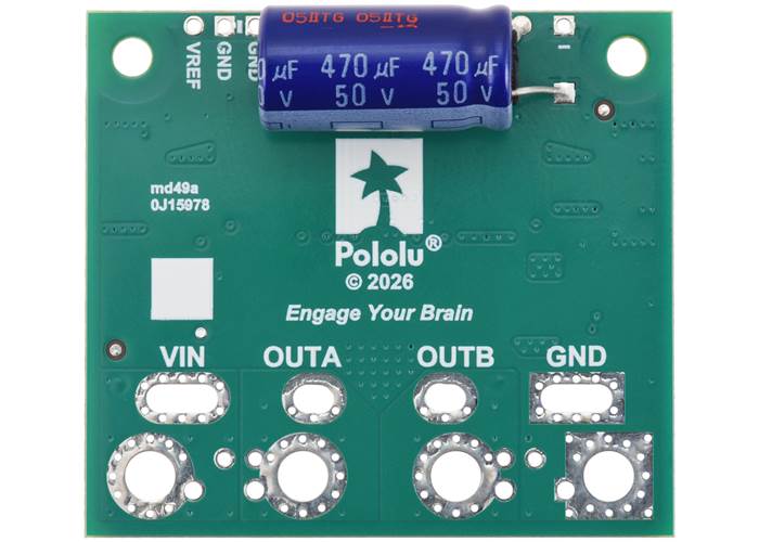
The driver includes three on-board 33 µF polymer capacitors across the motor supply, which are generally sufficient for brief tests and limited low-power operation, but adding a bigger capacitor across the motor supply and close to the motor driver is strongly recommended for most applications. We generally recommend using a capacitor of at least a few hundred μF and rated well above the maximum supply voltage; the required capacitance will be greater if the power supply is poor or far (more than about a foot) from the driver, and it will also depend on other factors like motor characteristics and applied PWM frequency. A through-hole capacitor can be installed directly on the board in the holes labelled '+' and '−' (connected to reverse-voltage-protected VM and GND, respectively); these holes are spaced to accommodate lead pitches of 3.5 mm, 5 mm, or 7.5 mm, depending on the specific pair used. A capacitor can also be installed across VIN and GND at or near the board, but please note that this would position the capacitor outside of the board’s reverse voltage protection. The pictures below show some examples of adding capacitors to the top and bottom side of the board:

Example of adding a capacitor to the Pololu G2 High-Power Motor Driver 24v30 CS. (1)

Example of adding a capacitor to the Pololu G2 High-Power Motor Driver 24v30 CS.
Example of adding a capacitor to the back side of the Pololu G2 High-Power Motor Driver 24v30 CS.
Example of adding a capacitor to the back side of the Pololu G2 High-Power Motor Driver 24v30 CS. (1)
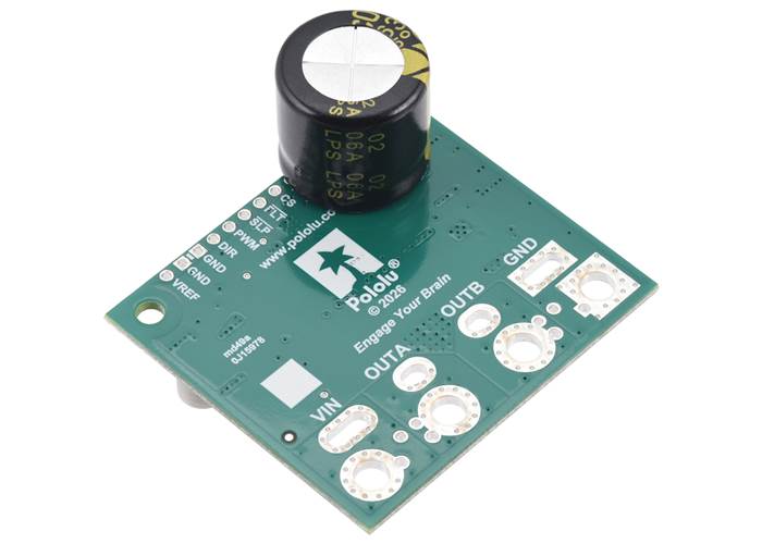
Example of adding a capacitor to the back side of the Pololu G2 High-Power Motor Driver 24v30 CS. (2) (2)
Warning: Take proper safety precautions when using high-power electronics. Make sure you know what you are doing when using high voltages or currents! During normal operation, this product can get hot enough to burn you. Take care when handling this product or other components connected to it.
With the PWM pin held low, both motor outputs will be held low (a brake operation). With PWM high, the motor outputs will be driven according to the DIR input. This allows two modes of operation: sign-magnitude, in which the PWM duty cycle controls the speed of the motor and DIR controls the direction, and locked-antiphase, in which a pulse-width-modulated signal is applied to the DIR pin with PWM held high.
In locked-antiphase operation, a low duty cycle drives the motor in one direction, and a high duty cycle drives the motor in the other direction; a 50% duty cycle turns the motor off. A successful locked-antiphase implementation depends on the motor inductance and switching frequency smoothing out the current (e.g. making the current zero in the 50% duty cycle case), so a high PWM frequency might be required.
| Motor Driver Truth Table | ||||
|---|---|---|---|---|
| PWM | DIR | OUTA | OUTB | Operation |
| H | H | H | L | Forward |
| H | L | L | H | Reverse |
| L | X | L | L | Brake |
The motor driver supports PWM frequencies as high as 100 kHz, but note that switching losses in the driver will be proportional to the PWM frequency. Typically, around 20 kHz is a good choice for sign-magnitude operation since it is high enough to be ultrasonic, which results in quieter operation.
A pulse on the PWM pin must be high for a minimum duration of approximately 0.5 µs before the outputs turn on for the corresponding duration (any shorter input pulse does not produce a change on the outputs), so low duty cycles become unavailable at high frequencies. For example, at 100 kHz, the pulse period is 10 µs, and the minimum non-zero duty cycle achievable is 0.5/10, or 5%.
The G2 24v30 CS includes an Allegro ACS37220LEZATR-100B3 ±100A Hall effect current sensor on the OUTB motor output, and this sensor outputs a voltage proportional to the motor current and VCC voltage on the motor driver’s CS pin. The CS voltage, VCS, is centred at 1.65 V when there is no current flowing and changes by approximately 13.2 mV per amp of motor current. Current flowing from OUTA to OUTB is considered positive and increases VCS, while current flowing from OUTB to OUTA decreases VCS:
``V_"OUT" = 1.65 text(V) + 0.0132 text(V)/text(A) * I_"A→B"``
``I_"A→B" = (V_"OUT" – 1.65 text(V)) / (0.0132 text(V)/text(A)) = (V_"OUT" – 1.65 text(V)) * 75.8 text(A)/text(V)``
For more details on the current sensor, see the ACS37220 datasheet (2MB pdf). We also have standalone carriers for this current sensor available in compact and large form factors.
The G2 driver has the ability to limit the motor current through current chopping: once the motor drive current reaches a set threshold, the driver goes into brake mode (slow decay) for about 25 µs before applying power to drive the motor again. This makes it more practical to use the driver with a motor that might only draw around ten amps while running but can draw many times that amount while starting.
The current limiting threshold is nominally set to about 100 A by default. You can lower the limit by connecting an additional resistor between the VREF pin and the adjacent GND pin; the graph below shows how the current limit relates to the VREF resistor value. For example, adding a 100 kΩ resistor between VREF and GND lowers the current limit to approximately 55 A. Note that the current limiting threshold is not very precise, and it is even less accurate at low settings (indicated by the dashed portion of the curve).
 |
The motor driver can detect several fault states that it reports by driving the FLT pin low; this is an open-drain output that should be pulled up to your system’s logic voltage. The detectable faults include short circuits on the outputs, under-voltage, and over-temperature. All of the faults disable the motor outputs but are not latched, meaning the driver will attempt to resume operation when the fault condition is removed (or after a delay of a few milliseconds in the case of the short circuit fault). The over-temperature fault provides a weak indication of the board being too hot, but it does not directly indicate the temperature of the MOSFETs, which are usually the first components to overheat, so you should not count on this fault to prevent damage from over-temperature conditions.

Thermal image of a high-current test.
The MOSFETs on this driver can handle large current spikes for short durations (e.g. 200 A for a few milliseconds), and the driver’s current chopping will help keep the average current under 100 A or whatever lower limit has been set via VREF. The actual current you can deliver for longer durations than quick transients will depend on how well you can keep the driver cool, and the carrier’s printed circuit board is designed to help with this by drawing heat out of the MOSFETs. In our tests at room temperature and with no forced air flow, the driver was able to deliver 30 A for several minutes without the MOSFETs exceeding 125°C. Performance can be improved by adding a heat sink or forced air flow, and performance will be derated for operation in confined spaces or higher ambient temperatures.
Warning: This motor driver has no over-temperature shut-off, and an over-temperature condition can cause permanent damage to the motor driver. If you expect to be operating near the rated limits, we recommend monitoring the MOSFETs’ temperature and looking into adding additional cooling if necessary. We also recommend using the driver’s integrated current sensor to monitor your current draw.
| Size: | 1.7″ × 1.9″ × 0.37″ |
|---|---|
| Weight: | 12 g |
| Motor channels: | 1 |
|---|---|
| Minimum operating voltage: | 6.5 V |
| Maximum operating voltage: | 40 V1 |
| Continuous output current per channel: | 30 A |
| Peak output current per channel: | 100 A2 |
| Current sense: | 0.0132 V/A |
| Maximum PWM frequency: | 100 kHz |
| Minimum logic voltage: | 1.8 V |
| Maximum logic voltage: | 5.5 V |
| Reverse voltage protection?: | Y |
| PCB dev codes: | md49a |
|---|---|
| Other PCB markings: | 0J15978 |
This DXF drawing shows the locations of all of the board’s holes.