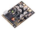
This shield makes it easy to control two high-power DC motors with your Arduino or Arduino-compatible board. Its twin discrete MOSFET H-bridges support a wide 6.5 V to 40 V operating range and are efficient enough to deliver a continuous 18 A without a heat sink.
Special Order
Shipping from $9.90
+27 more from our supplier in 7-10 days
Our Code: SKU-004380
Supplier Link: [Pololu MPN:2518]
This shield makes it easy to control two high-power DC motors with your Arduino or Arduino-compatible board. Its twin discrete MOSFET H-bridges support a wide 6.5 V to 40 V operating range and are efficient enough to deliver a continuous 18 A without a heat sink. The drivers offer basic current sensing and current limiting functionality, and they accept ultrasonic PWM frequencies for quieter operation. The Arduino pin mappings can all be customized if the defaults are not convenient, and the motor driver control lines are broken out along the left side of the shield for general-purpose use without an Arduino.
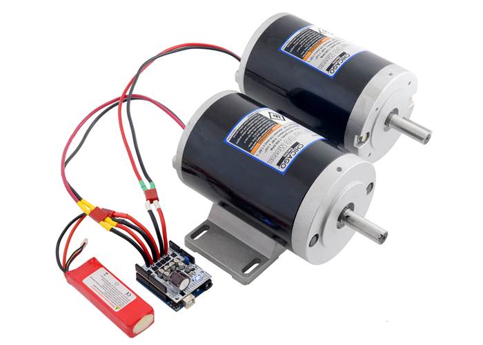
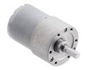
Pololu Dual G2 High-Power Motor Driver Shield controlling a pair of high-power motors.
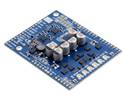
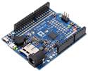
The G2 family of dual high-power motor driver shields features pairs of discrete MOSFET H-bridges designed to drive two large brushed DC motors. They have the form factor of an Arduino shield, so they can plug directly into an Arduino or compatible board, such as the A-Star 32U4 Prime, but they also break out all of the motor driver pins along the left side of the board to enable use as a general-purpose motor driver without an Arduino. Four versions are available so you can pick the one with the appropriate operating voltage range and output current capabilities for your project:
 Dual G2 High- Power Motor Driver 18v22 Shield |
 Dual G2 High- Power Motor Driver 18v18 Shield |
 Dual G2 High- Power Motor Driver 24v18 Shield |
 Dual G2 High- Power Motor Driver 24v14 Shield |
|
|---|---|---|---|---|
| Absolute max input voltage: |
30 V | 40 V | ||
| Max nominal battery voltage: |
18 V | 28 V | ||
| Max continuous current per channel: |
22 A | 18 A | 18 A | 14 A |
| Default active current- limiting threshold: |
60 A | 50 A | 40 A | |
| Current sense output: |
10 mV/A | 20 mV/A | ||
The minimum operating voltage for all four versions is 6.5 V. The maximum operating voltages are given in the above table; they are well above what typical Arduinos can tolerate, so the shields include an integrated 7.5 V, 1 A switching step-down regulator that can optionally be used to power whatever Arduino or Arduino-compatible board it is plugged into, enabling operation from a single power supply. This regulator can also be configured to output 5 V for applications where that would be more useful than the default 7.5 V, and the Arduino pin mappings can all be customised if the defaults are not convenient.
These dual motor drivers are also available as Raspberry Pi expansion boards. For single-channel versions in a more compact form factor, consider our High-Power Motor Drivers. For a lower-power, lower-cost alternative Arduino shield, please consider the Dual MC33926 Motor Driver Shield.
Pololu Dual G2 High-Power Motor Driver 24v18 Shield for Arduino. (1) |
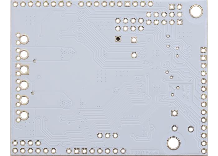
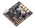
Pololu Dual G2 High-Power Motor Driver 18v22 or 24v18 Shield for Arduino, bottom view. |
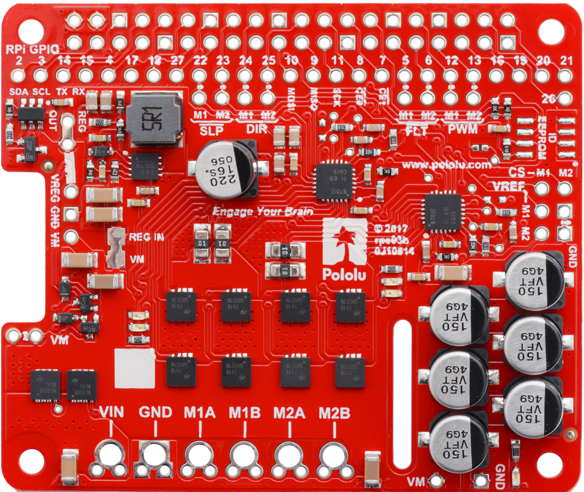
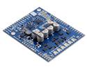
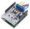
Pololu Dual G2 High-Power Motor Driver 24v18 Shield for Arduino. |
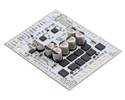
This version, the 24v18 motor driver shield, can be distinguished from the other versions by its white PCB and the number 100 on top of the tall silver electrolytic capacitors.
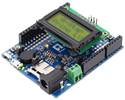
Pololu Dual G2 High-Power Motor Driver Shield being controlled by an A-Star 32U4 Prime.
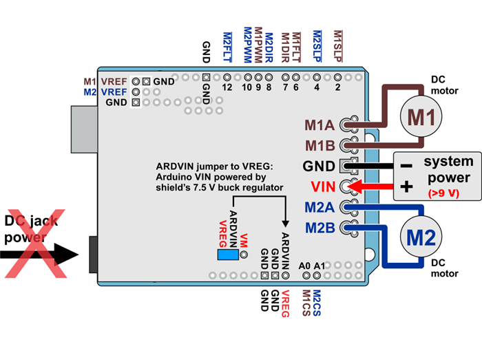
Dual G2 high-power motor driver shield powering an Arduino with the shield’s 7.5 V regulator (VREG). |
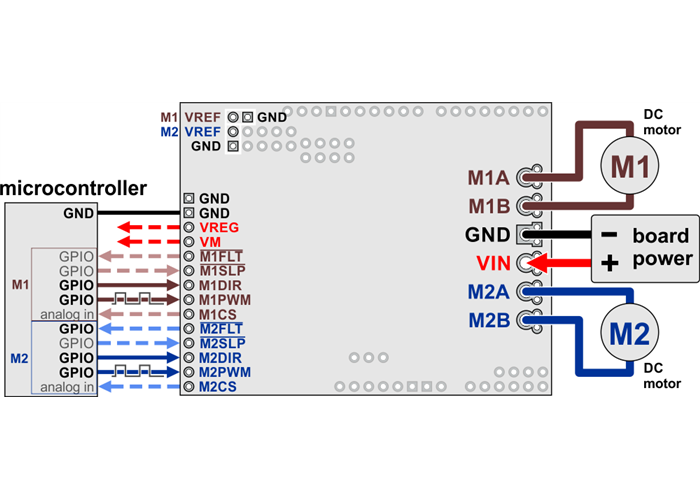
Dual G2 high-power motor driver shield connected to a microcontroller (dashed connections are optional). |
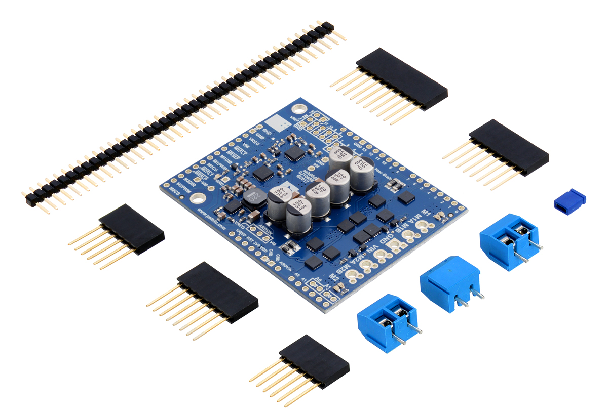 |
Pololu Dual G2 High-Power Motor Driver 18v18 Shield for Arduino with included hardware. |
|---|
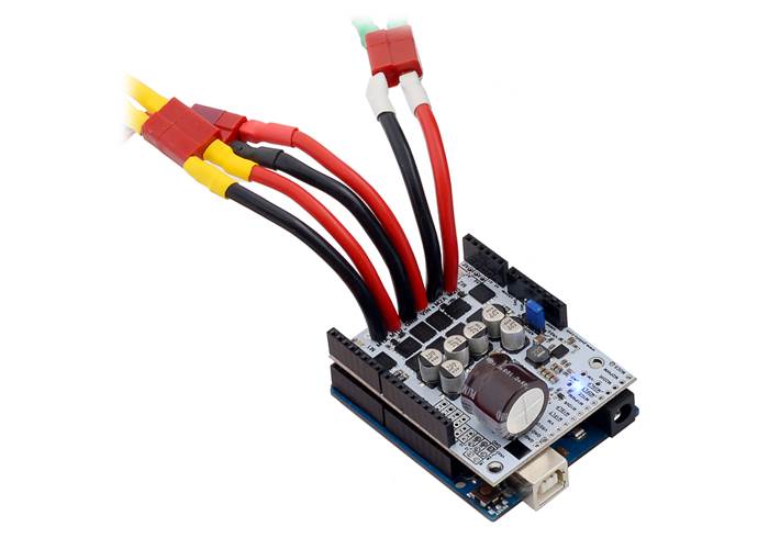
For high-current installations, motor and power supply wires should be soldered directly to the driver (the supplied terminal blocks are only rated for up to 16 A).
This motor driver board ships with all of the surface-mount parts populated. However, soldering is required for assembly of the included through-hole parts. The following through-hole parts are included:
A 0.1″ shorting block (for optionally supplying shield power to Arduino) is also included.
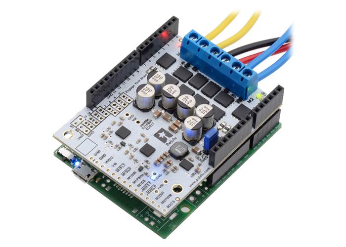
You can solder the terminal blocks to the six large through-holes to make your motor and motor power connections, or you can break off a 1×12 section of the 0.1″ header strip and solder it into the smaller through-holes that border these larger holes. Note, however, that the terminal blocks are only rated for 16 A, and each header pin pair is only rated for a combined 6 A, so for higher-power applications, thick wires should be soldered directly to the board, and appropriately high-current connectors (like these) should be used.
When not using this board as an Arduino shield, you can solder the 0.1″ headers to the logic connections along the left side of the board to enable use with custom cables or solderless breadboards, or you can solder wires directly to the board for more compact installations. Note that motor and motor power connections should not be made through a breadboard.
The motor driver includes six 100 µF or 150 µF electrolytic power capacitors, and there is room to add additional capacitors (e.g. to compensate for long power wires or increase stability of the power supply). Additional power capacitors are usually not necessary, and no additional capacitors are included with this motor driver.
The two mounting holes are intended for use with #4 screws (not included).
The driver’s current sense pins, M1CS and M2CS, output voltages proportional to the motor currents while the H-bridge is driving. The output voltage is about 10 mV/A for the 18v22 version and 20 mV/A for the other versions, plus a small offset, which is typically about 50 mV.
The driver has the ability to limit the motor current through current chopping: once the motor drive current reaches a set threshold, the driver goes into brake mode (slow decay) for about 25 µs before applying power to drive the motor again. This makes it more practical to use the driver with a motor that might only draw a few amps while running but can draw many times that amount (tens of amps) when starting. You can lower the default current limit threshold by connecting an additional resistor between the VREF pin and the adjacent GND pin.
See the user’s guide for more information on current sense feedback and current limiting.
The MOSFETs on this driver can handle large current spikes for short durations (e.g. 100 A for a few milliseconds), and the driver’s current chopping will help keep the average current under the set current limit. The actual current you can deliver for longer durations than quick transients will depend on how well you can keep the driver cool, and the carrier’s printed circuit board is designed to help with this by drawing heat out of the MOSFETs. The continuous current ratings we provide for these drivers are based on our tests in still air at room temperature. Performance can be improved by adding a heat sink or forced air flow, and performance will be derated for operation in confined spaces or higher ambient temperatures. For high-current installations, the motor and power supply wires should also be soldered directly instead of going through the supplied terminal blocks, which are rated for up to 16 A.
Warning: This motor driver has no over-temperature shut-off, and an over-temperature condition can cause permanent damage to the motor driver. If you expect to be operating near the rated limits, we recommend monitoring the MOSFETs’ temperature and looking into adding additional cooling if necessary. We also recommend using the driver’s integrated current sense output or an external current sensor to monitor your current draw.
This product can get hot enough to burn under normal operating conditions. Take care when handling this product and other components connected to it.
The following table provides a general comparison of the G2 and H2 drivers, which are available in six single-channel versions and eight dual-channel versions. Four of the dual-channel drivers have the form factor of an Arduino shield, but they can also be used with other controllers as general-purpose motor drivers. The other four dual-channel drivers are in the form factor of a Raspberry Pi HAT and compatible Raspberry Pi boards (Model B+ or newer). The single-channel G2 drivers all have the same form factor except for the highest-power 24v30, which is larger to accommodate the much larger MOSFETs. We also have a higher-voltage, single-channel H2 high-power motor driver with the same form factor as the single-channel G2 drivers, but the control interface and some aspects of the operation are different.
| G2 and H2 High-Power Motor Drivers | ||||||||||
|---|---|---|---|---|---|---|---|---|---|---|
 G2 18v17 |
 G2 18v25 |
 G2 24v13 |
 G2 24v21 |
 G2 24v30 CS |
 H2 36v11 CS |
 G2 18v18 |
 G2 18v22 |
 G2 24v14 |
 G2 24v18 |
|
| Motor channels | single (1) | dual (2) | ||||||||
| Min. operating voltage | 6.5 V | 5 V | 6.5 V | |||||||
| Absolute max. input voltage | 30 V | 40 V | 60 V | 30 V | 40 V | |||||
| Max. nominal battery voltage | 18 V | 28 V | 36 V | 18 V | 28 V | |||||
| Max. continuous current(1) | 17 A | 25 A | 13 A | 21 A | 30 A | 11 A | 18 A | 22 A | 14 A | 18 A |
| Current sense feedback | 20 mV/A | 10 mV/A | 40 mV/A | 20 mV/A | 13.2 mV/A | 60 mV/A(2) | 20 mV/A | 10 mV/A | 20 mV/A | 20 mV/A |
| Direct motor current measurement |
— | — | — | — | — | — | — | — | ||
| Default current limit(3) | 40 A | 60 A | 30 A | 50 A | 100 A | n/a | 50 A | 60 A | 40 A | 50 A |
| Size | 1.3″ × 0.8″ | 1.7″ × 1.9″ | 1.3″ × 0.8″ | 2.56″ × 2.02″ | ||||||
| Shield version available? | — | — | — | — | — | — | Yes | Yes | Yes | Yes |
| Raspberry Pi expansion version available? |
— | — | — | — | — | — | Yes | Yes | Yes | Yes |
| 1-piece price | $44.95 | $56.95 | $44.95 | $56.95 | $74.95 | $56.95 | $74.95 | $104.95 | $79.95 | $104.95 |
| Note 1: Per motor channel, at room temperature and without heat sinking or forced air flow. | ||||||||||
| Note 2: When VCC = 5 V; sensitivity is proportional to VCC. | ||||||||||
| Note 3: Can be adjusted lower. | ||||||||||
|
|
|
Pololu Dual G2 High-Power Motor Driver 24v18 Shield for Arduino. (1) |
|
|
Note: As an alternative to these motor drivers, our Simple Motor Controllers have similar power characteristics and offer high-level interfaces (e.g. USB, RC hobby servo pulses, analogue voltages, and TTL serial commands) that make them easier to use for some applications.
| Size: | 2.56″ × 2.02″ × 0.38″1 |
|---|---|
| Weight: | 19 g1 |
| Motor channels: | 2 |
|---|---|
| Minimum operating voltage: | 6.5 V |
| Maximum operating voltage: | 40 V2 |
| Continuous output current per channel: | 18 A3 |
| Current sense: | 0.020 V/A |
| Maximum PWM frequency: | 100 kHz |
| Minimum logic voltage: | 1.8 V |
| Maximum logic voltage: | 5.5 V |
| Reverse voltage protection?: | Y |
| PCB dev codes: | ash06c |
|---|---|
| Other PCB markings: | 0J10697, blank white box |
User’s manual for the Pololu Dual G2 High-Power Motor Driver Shields for Arduino.
This DXF drawing shows the locations of all of the board’s holes.
This DXF drawing shows the locations of all of the board’s holes.
This library for the Arduino makes it easy to interface with Pololu’s Dual G2 High-Power Motor Driver Shields and drive a pair of high-power, brushed DC motors. A sample sketch is included with the library.