This module protects a connected load from reverse voltages down to -60 V. This version does not block reverse current, making it suitable for applications such as battery-powered motor control where delivering energy back into the supply is desirable.
Special Order
Shipping from $4.90
+586 more from our supplier in 7-10 days
Our Code: SKU-010699
Supplier Link: [Pololu MPN:5381]
This module protects a connected load from reverse voltages down to -60 V. This version does not block reverse current, making it suitable for applications such as battery-powered motor control where delivering energy back into the supply is desirable.
| Operating voltage1 | Max current | Resistance2 | Reverse current blocking | Size |
|---|---|---|---|---|
| 4 V – 60 V | 12 A | < 5 mΩ | no | 0.3″×0.5″ |
Note 1: Operates down to 3.2 V after startup.
Note 2: MOSFET on resistance.
Pololu Reverse Voltage Protectors are compact modules that can be inserted between a power supply and its load to protect that load from damage in the case of accidental reversal of power polarity. They operate from 4 V (3.2 V after startup) to 60 V (green PCBs) or 75 V (red PCBs) and provide protection from negative voltages down to -60 V or -75 V, respectively. They are available in different power levels and with or without reverse current blocking:
| Function | Max voltage |
Max current |
MOSFET on resistance |
Size | Price | Pololu Item # |
|---|---|---|---|---|---|---|
| Reverse voltage protection only | 75 V | 8 A | < 15 mΩ | 0.3″×0.5″ | $3.95 | #5358 |
| 17 A | < 3 mΩ | 0.435″×0.7″ | $7.95 | #5359 | ||
| 60 V | 10 A | < 10 mΩ | 0.3″×0.5″ | $3.29 | #5380 | |
| 12 A | < 5 mΩ | $4.39 | #5381 | |||
| 20 A | < 3 mΩ | 0.435″×0.7″ | $5.95 | #5386 | ||
| 25 A | < 1.5 mΩ | $7.95 | #5387 | |||
| Reverse voltage and current protection (ideal diode) |
60 V | 10 A | < 10 mΩ | 0.3″×0.5″ | $3.79 | #5382 |
| 12 A | < 5 mΩ | $4.95 | #5383 | |||
| 20 A | < 3 mΩ | 0.435″×0.7″ | $6.49 | #5388 | ||
| 25 A | < 1.5 mΩ | $8.49 | #5389 | |||
| Ideal diode pair for ORing power | 60 V | 6 A per channel | < 10 mΩ | 0.75″×0.775″ | $7.95 | #5398 |
The versions without reverse current blocking are suitable for applications such as battery-powered motor control where the ability to deliver energy back into the supply is desirable. The versions with reverse current blocking act as ideal diodes, preventing any current from flowing from the load back into the supply.
|
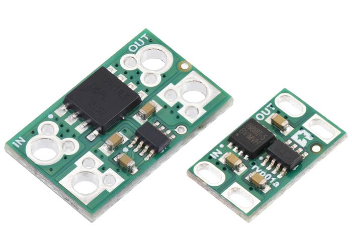
60V-max Pololu Reverse Voltage Protectors are available in 20A/25A (left) and 10A/12A (right) versions. |
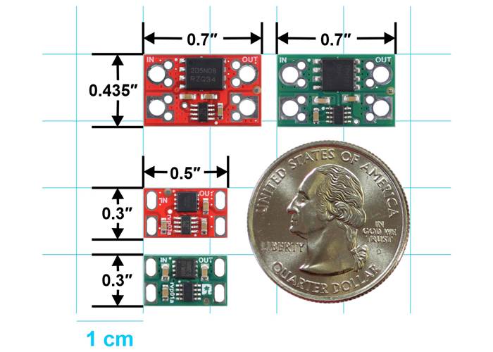
Size comparison of the Pololu Reverse Voltage Protectors: 75V, 17A (larger red PCB); 60V, 20A/25A (larger green PCB); 75V, 8A (smaller red PCB); and 60V, 10A/12A (smaller green PCB). |
|
Note: Any voltage on the output will reduce the 60 V maximum rating. For example, if there is a large capacitor charged to 24 V on the ouput, the minimum negative voltage would be -36 V.
Pololu Reverse Voltage Protector, 4-60V, 12A, top view. |
Pololu 10A/12A Reverse Voltage Protector/Ideal Diode Reverse Voltage Protector, bottom view. |
This module uses an LM74500-Q1 reverse voltage protection controller and N-channel MOSFET to provide protection from negative voltages down to -60 V. It operates from 4 V (3.2V after startup) to 60 V and has a VIN path impedance of approximately 5 mΩ when the MOSFET is on (i.e. when power is connected with the proper polarity), enabling currents up to around 12 A continuous (and up to around 40 A for a few seconds). This version does not block reverse current, making it suitable for applications such as battery-powered motor control where delivering energy back into the supply is desirable.
| Operating voltage | Max current | MOSFET on resistance | Reverse current blocking | Size |
|---|---|---|---|---|
| 4 V – 60 V* | 12 A | < 5 mΩ | no | 0.3″×0.5″ |
| * Operates down to 3.2 V after startup. | ||||

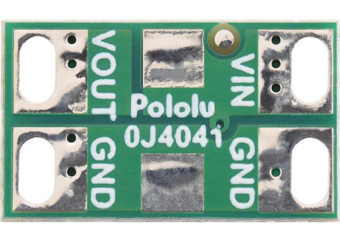
Pololu 10A/12A Reverse Voltage Protector pinout.
Supply power and ground connect to the VIN and GND side of the board, and the VOUT and GND pins connect to the load. If the supply is connected correctly, with its positive voltage on VIN, the power will pass through the board to VOUT. If the supply is connected incorrectly, with the positive voltage on GND, supply power will not pass through to the output, and any connected load will be protected from the reversed supply voltage.
The input and output slots can accommodate a variety of connectors, including 5mm-pitch terminal blocks, 3.5mm-pitch terminal blocks, 0.2″-pitch headers, and 0.1″-pitch headers.
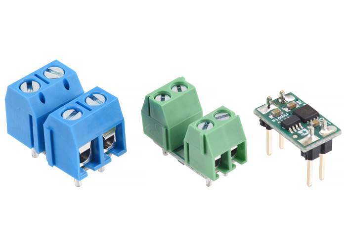
Examples of various connectors that can be used with the Pololu 10A/12A Reverse Voltage Protectors (from left to right: 5mm terminal blocks, 3.5mm terminal blocks, 0.1″ headers).
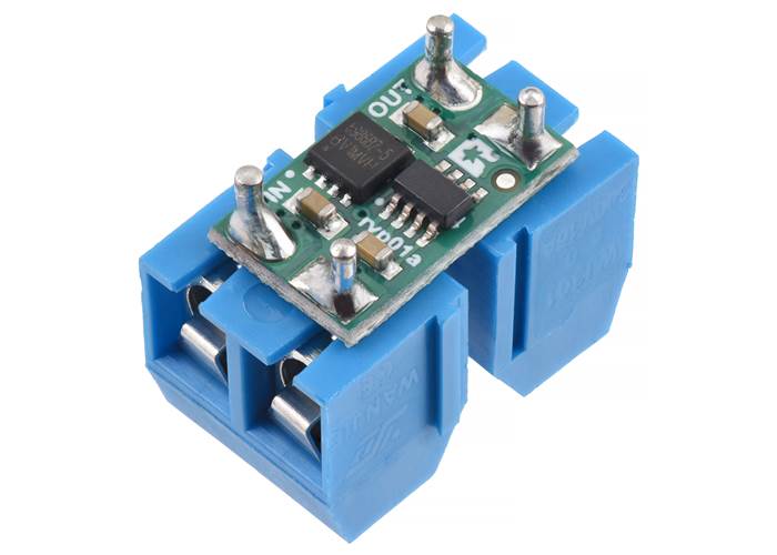
Pololu 10A/12A Reverse Voltage Protector soldered to a pair of two-pin, 5mm-pitch screw terminal blocks (not included). |
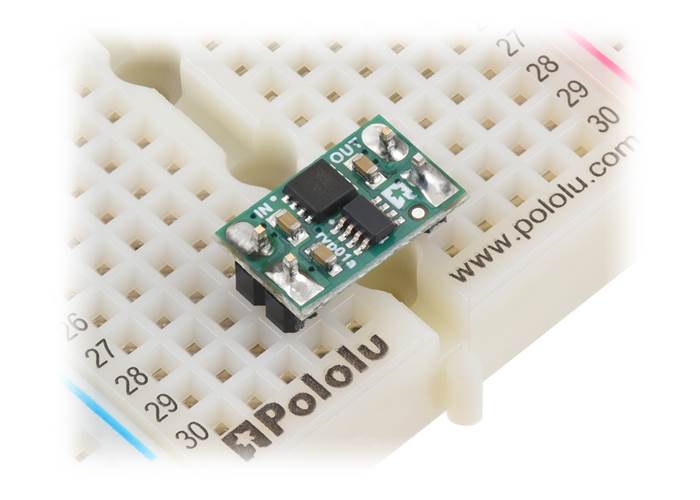
Pololu 10A/12A Reverse Voltage Protector soldered with 0.1″ male headers (not included) for use in a breadboard. |
There are pads for adding an optional SMB-size transient voltage suppressor (TVS) across VIN and GND on the bottom side of the board:
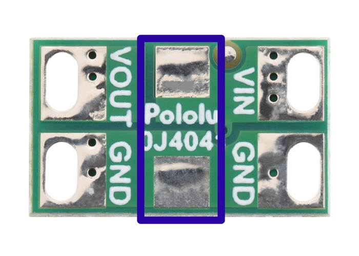
There are pads for adding an optional SMB-size transient voltage suppressor (TVS) across VIN and GND on the bottom of the Pololu 10A/12A Reverse Voltage Protectors.
We can manufacture these with the TVS diode of your choice for custom high-volume orders (typically at least a few hundred pieces). If you are interested in such a customisation, please contact us for a quote.

Schematic diagram of the 60V Pololu Reverse Voltage Protectors (green PCBs).
| Size: | 0.3″ × 0.5″ × 0.08″ |
|---|---|
| Weight: | 0.2 g |
| Minimum operating voltage: | 4 V1 |
|---|---|
| Maximum operating voltage: | 60 V |
| Maximum current: | 12 A |
| Reverse current blocking: | N |
| Version: | 60V, 12A |
| PCB dev codes: | rvp01a |
|---|---|
| Other PCB markings: | 0J4041 |
This DXF drawing shows the locations of all of the board’s holes.