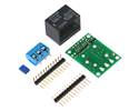
This RC switch converts hobby radio control pulses to digital on/off signals for use in RC switch and simple RC adaptor applications. One output indicates the presence of a valid RC signal, and the other indicates whether the switch is active.
Special Order
Shipping from $9.90
+350 more from our supplier in 7-10 days
Our Code: MCU-60159
Supplier Link: [Pololu MPN:2801]
This RC switch converts hobby radio control pulses to digital on/off signals for use in RC switch and simple RC adapter applications. One output indicates the presence of a valid RC signal, and the other indicates whether the switch is active. The activation threshold and direction are configurable, and a safe-start feature reduces the likelihood of unexpected activation.

Pololu RC Switch with Digital Output, bottom view with dimensions.

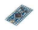
Pololu RC Switch with Digital Output, labeled top view.
The Pololu RC switch with Digital Output can be used with standard hobby radio control systems for radio control switch applications or simple interface applications. For example, this module can be used to convert unused RC receiver or servo controller channels to simple high/low signals that can control LEDs, MOSFETs, or relays, or it can serve as a simple interface between RC systems and microcontrollers that do not have the necessary resources for decoding hobby RC servo pulses. Two digital outputs indicate the presence of a valid signal and whether the switch is on or off.
The board requires a 2.5–5.5 V power source supplied to VCC. The board can be powered by whatever digital system is reading the output, or it can be powered from the RC receiver if you bridge the surface-mount jumper on the bottom of the board that connects VRC to VCC.
The RC switch measures the width of incoming RC pulses and compares it to a user-configurable threshold (with ±64 µs of hysteresis) to decide whether to turn the output. By default, the threshold is approximately 1700 μs, with switch activation occurring above the threshold (longer pulses), but the switch has a learning mode that allows you to change the threshold and the activation direction. A safe-start feature reduces the likelihood of unexpected activation.
This compact unit measures 0.4″ × 0.4″ and weighs 0.3 g (0.01 oz) without the included header pins.

Typical wiring diagram for the Pololu RC Switch with Digital Output.
The RC switch provides feedback about what state it is in via a yellow indicator LED. Status information is also provided on two output pins:
Each of the these outputs can source or sink up to 25 mA. More information about using the Pololu RC switch with Digital Output can be found in the user’s guide.
A 7-pin 0.1″ straight breakaway male header is included with the Pololu RC switch with Digital Output. The header pins can be used to connect the RC switch to perfboards or breadboards, or you can solder wires directly to the board for the most compact installation.
Pololu RC Switch with Digital Output with included hardware. |
Pololu RC Switch with Digital Output on a breadboard. |
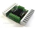
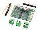
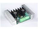
We offer two versions of this switch with integrated MOSFETS that can switch loads directly: RC switch with a small MOSFET and RC switch with a medium MOSFET (the latter of which also has an integrated voltage regulator). We also offer an RC switch with a relay that can be used to control electrically isolated loads.
This product replaces item #752. (For most applications, it can be considered a drop-in replacement for #752.)
 |
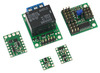
The Pololu RC Switch family of products. |
|---|
| Size: | 0.4″ × 0.4″ |
|---|---|
| Weight: | 0.3 g1 |
| Max current on a single I/O: | 25 mA |
|---|---|
| Minimum logic voltage: | 2.5 V |
| Maximum logic voltage: | 5.5 V |
| PCB dev codes: | rcs01b |
|---|---|
| Other PCB markings: | 0J7707 |
User’s manual for the Pololu RC Switch with Medium Low-Side MOSFET and the Pololu RC Switch with Relay.
Printable schematic diagram of the Pololu RC Switch with Digital Output.
This DXF drawing shows the locations of all of the board’s holes.