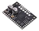
This version of our STSPIN220 Low-Voltage Stepper Motor Driver Carrier ships with male header pins installed , so no soldering is required to use it with an appropriate 16-pin socket or solderless breadboard.
In stock in Australia
Shipping from $4.90
+24 more from our supplier in 7-10 days
Our Code: SKU-005270
Supplier Link: [Pololu MPN:2877]
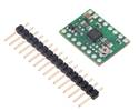
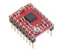
This version of our STSPIN220 Low-Voltage Stepper Motor Driver Carrier ships with male header pins installed, so no soldering is required to use it with an appropriate 16-pin socket or solderless breadboard. Please see the STSPIN220 Low-Voltage Stepper Motor Driver Carrier product page for more information about the driver.
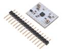
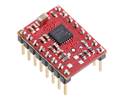
This version of our STSPIN220 Low-Voltage Stepper Motor Driver Carrier ships with male header pins installed as shown in the main product picture, so no soldering is required to use it with an appropriate 16-pin socket or solderless breadboard. Please see the STSPIN220 Low-Voltage Stepper Motor Driver Carrier product page for more information about the driver.
| Size: | 0.6″ × 0.8″ |
|---|---|
| Weight: | 2.5 g |
| Motor driver: | STSPIN220 |
|---|---|
| Minimum operating voltage: | 1.8 V |
| Maximum operating voltage: | 10 V |
| Continuous current per phase: | 1.1 A |
| Maximum current per phase: | 1.3 A |
| Minimum logic voltage: | 1.6 V |
| Maximum logic voltage: | 5.5 V |
| Microstep resolutions: | full, 1/2, 1/4, 1/8, 1/16, 1/32, 1/64, 1/128, 1/256 |
| Current limit control: | potentiometer |
| Reverse voltage protection?: | N |
| Header pins soldered?: | Y |
| PCB dev codes: | md39a |
|---|---|
| Other PCB markings: | 0J11899 |
This DXF drawing shows the locations of all of the board’s holes.
The STSPIN220’s integrated sequencer can provide a resolution up to 256 microsteps, but it is always possible to switch to the full-step operation on-the-fly. This document describes how to select the step resolution and manage the switch between the microstep and full-step operation.
STMicro’s product page for the STSPIN220 low-voltage stepper motor driver, with links to its most up-to-date datasheet and other resources.
No, a low-voltage stepper motor driver is not your only option. To avoid damaging your stepper motor, you want to avoid exceeding the rated current, which is 600 mA in this instance. All of our stepper motor drivers let you limit the maximum current, so as long as you set the limit below the rated current, you will be within spec for your motor, even if the voltage exceeds the rated voltage. (For example, driving a 3.9 V motor with a DRV8825, and using a supply voltage higher than the DRV8825’s minimum of 8.2 V, will not damage the motor as long as the current limit is set appropriately.)
The voltage rating is just the voltage at which each coil draws the rated current, so the coils of your stepper motor will draw 600 mA at 3.9 V. By using a higher voltage along with active current limiting, the current is able to ramp up faster, which lets you achieve higher step rates than you could using the rated voltage.
However, if you still want to use a lower motor supply voltage for other reasons, our DRV8834 or STSPIN-220 low-voltage stepper motor drivers are appropriate choices.
Yes, you do! Setting the current limit on your stepper motor driver carrier before connecting your motor is essential to making sure that it runs properly. An appropriate current limit also ensures that your motor is not allowed to draw more current than it or your driver can handle, since that is likely to damage one or both of them.
Setting the current limit on this stepper motor driver is done by adjusting the on-board potentiometer. We strongly recommend using a multimeter to measure the VREF voltage while setting the current limit so you can be sure you set it to an appropriate value (just turning the pot randomly until things seem to work is not a good approach). The following video has more details on setting the current limit: