Output voltage Typical max output current 1 Input voltage range 2 12 V 600 mA 12.2 V – 50 V Note 1: Actual achievable continuous output current is a function of input voltage and is limited by thermal dissipation.
Special Order
Shipping from $4.90
+900 more from our supplier in 7-10 days
Our Code: SKU-004932
Supplier Link: [Pololu MPN:3796]
| Output voltage | Typical max output current1 | Input voltage range2 |
|---|---|---|
| 12 V | 600 mA | 12.2 V – 50 V |
Note 1: Actual achievable continuous output current is a function of input voltage and is limited by thermal dissipation. See the output current graphs on the product pages for more information.
Note 2: Minimum input voltage is subject to dropout voltage considerations; see the dropout voltage section of product pages for more information.
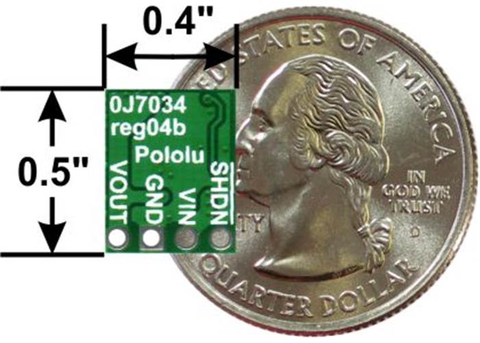
Pololu step-down voltage regulator D36V6Fx/D24V6Fx/D24V3Fx, bottom view with dimensions.
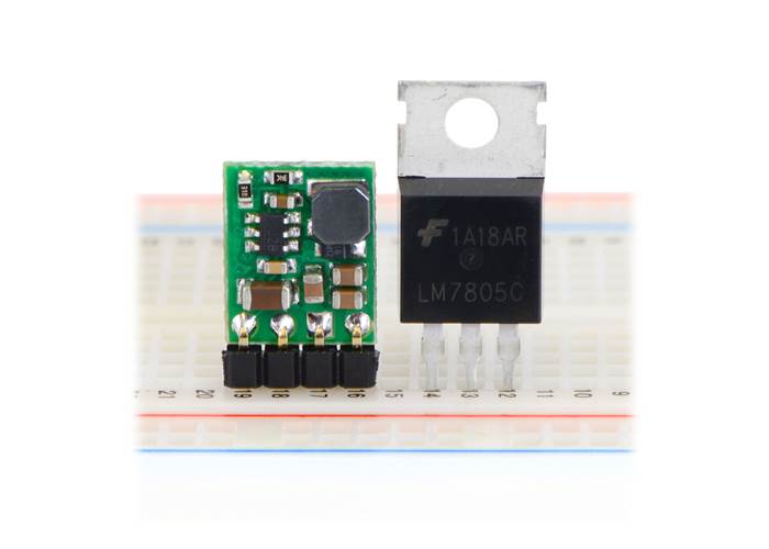
Pololu step-down voltage regulator D36V6Fx/D24V6Fx/D24V3Fx next to a 7805 voltage regulator in TO-220 package.
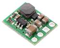
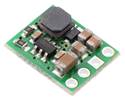
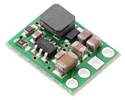
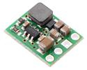
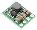
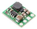
The D36V6x family of buck (step-down) voltage regulators generates lower output voltages from input voltages as high as 50 V. They are switching regulators (also called switched-mode power supplies (SMPS) or DC-to-DC converters), which makes them much more efficient than linear voltage regulators, especially when the difference between the input and output voltage is large. This family includes seven versions with fixed output voltages ranging from 3.3 V to 15 V and two adjustable versions that can be set using a trimmer potentiometer:
The regulators feature short-circuit/over-current protection, and thermal shutdown helps prevent damage from overheating. The boards do not have reverse-voltage protection.

Pololu step-down voltage regulators D36V6Fx/D24V6Fx/D24V3Fx in a breadboard.

Pololu step-down voltage regulator D36V6Fx/D24V6Fx/D24V3Fx in a breadboard.
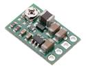
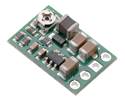
This regulator has four connections: shutdown (SHDN), input voltage (VIN), ground (GND), and output voltage (VOUT).
The SHDN pin can be driven low (under 1.25 V) to turn off the output and put the board into a low-power state (< 2 μA typical). The regulator is enabled by default, and this input can be left disconnected if you do not need this feature.
The input voltage, VIN, powers the regulator. Voltages between 4 V and 50 V can be applied to VIN, but for versions of the regulator that have an output voltage higher than 4 V, the effective lower limit of VIN is VOUT plus the regulator’s dropout voltage, which varies approximately linearly with the load (see below for graphs of the dropout voltage as a function of the load). Additionally, please be wary of destructive LC spikes (see below for more information).
The four connections are labelled on the back side of the PCB and are arranged with a 0.1″ spacing along the edge of the board for compatibility with solderless breadboards, connectors, and other prototyping arrangements that use a 0.1″ grid. You can solder wires directly to the board or solder in either the 4×1 straight male header strip or the 4×1 right-angle male header strip that is included.

Step-Down Voltage Regulator D36V6Fx with included 0.1″ male headers.
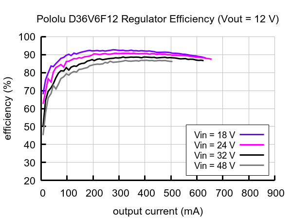
The efficiency of a voltage regulator, defined as (Power out)/(Power in), is an important measure of its performance, especially when battery life or heat are concerns.
 |
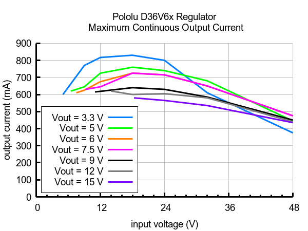
The maximum achievable output current of these regulators varies with the input voltage but also depends on other factors, including the ambient temperature, air flow, and heat sinking. The graph below shows maximum output currents that these regulators can deliver continuously at room temperature in still air and without additional heat sinking.
 |
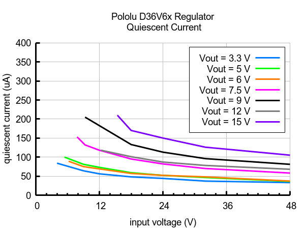
The quiescent current is the current the regulator uses just to power itself, and the graph below shows this for the different regulator versions as a function of the input voltage. The module’s SHDN input can be driven low to put the board into a low-power state where it typically draws under 2 μA.
 |
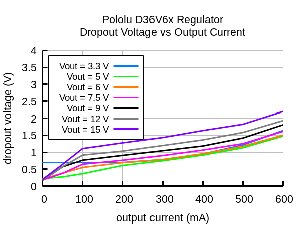
The dropout voltage of a step-down regulator is the minimum amount by which the input voltage must exceed the regulator’s target output voltage in order to ensure the target output can be achieved. For example, if a 5 V regulator has a 1 V dropout voltage, the input must be at least 6 V to ensure the output is the full 5 V. Generally speaking, the dropout voltage increases as the output current increases. The graph below shows the dropout voltages for the different members of this regulator family:
 |
When connecting voltage to electronic circuits, the initial rush of current can cause voltage spikes that are much higher than the input voltage. If these spikes exceed the regulator’s maximum voltage (50 V), the regulator can be destroyed. In our tests with typical power leads (~30″ test clips), input voltages above 28 V caused spikes over 50 V.
If you are connecting more than 28 V or your power leads or supply has high inductance, we recommend soldering a suitably rated 33 μF or larger electrolytic capacitor close to the regulator between VIN and GND.
More information about LC spikes can be found in our application note, Understanding Destructive LC Voltage Spikes.
| Size: | 0.4″ × 0.5″ × 0.1″1 |
|---|---|
| Weight: | 0.5 g1 |
| Minimum operating voltage: | 12.2 V2 |
|---|---|
| Maximum operating voltage: | 50 V |
| Maximum output current: | 600 mA |
| Output voltage: | 12 V |
| Reverse voltage protection?: | N |
| Maximum quiescent current: | 0.15 mA3 |
| Output type: | fixed 12V |
| PCB dev codes: | reg04b |
|---|---|
| Other PCB markings: | 0J7034 |
These DXF drawings show the locations of all of the holes on the fixed and adjustable Step-down Voltage Regulators D24V3x, D24V6x, and D36V6x.
This file contains 3D models (in the step file format) of the fixed and adjustable Step-down Voltage Regulators D24V3x, D24V6x, and D36V6x.