This is a breakout board for the MPS MP6602 microstepping bipolar/unipolar stepper motor driver, which features a serial interface and stall detection.
Special Order
Shipping from $4.90
+423 more from our supplier in 7-10 days
Our Code: SKU-011381
Supplier Link: [Pololu MPN:5688]
This is a breakout board for the MPS MP6602 microstepping bipolar/unipolar stepper motor driver, which features a serial interface and stall detection. It operates from 4.5 V to 35 V with a maximum current limit of 4 A, which it can run at continuously on our carrier board without a heat sink or forced air flow. The SPI interface allows configuration of the current limit, step mode (6 step modes from full-step through 1/32-step), decay mode off time, and stall detection, and it can also be used for stepper motor control. The driver also features built-in protection against under-voltage, over-current, and over-temperature conditions. This version does not include header pins.

MP6602 Stepper Motor Driver Carrier, bottom view with dimensions.
This product is a carrier board or breakout board for the MP6602 bipolar/unipolar stepper motor driver from Monolithic Power Systems (MPS); we therefore recommend careful reading of the MP6602GV datasheet (1MB pdf) before using this product. This stepper motor driver lets you control one bipolar stepper motor or unipolar stepper motor with up to a 4 A current limit without a heat sink or forced air flow (see the Power dissipation considerations section below for more information). Here are some of the driver’s key features:
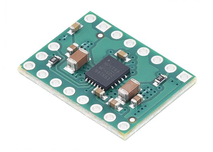
This product ships with all surface-mount components—including the MP6602 driver IC—installed as shown in the product picture.
We also have a variety of other stepper motor driver options in this same form factor with different operating profiles and features.
Note: The SPI interface is required for configuration of this driver’s control modes, so typical applications require a microcontroller that is capable of acting as an SPI master (either with an SPI peripheral or software SPI).
This version of the MP6602 Stepper Motor Driver Carrier does not have header pins soldered or included; 0.1″ headers are available separately, as is a version of this driver with header pins already soldered.
MP6602 Stepper Motor Driver Carrier. |
MP6602 Stepper Motor Driver Carrier, top view. |
MP6602 Stepper Motor Driver Carrier, bottom view. |
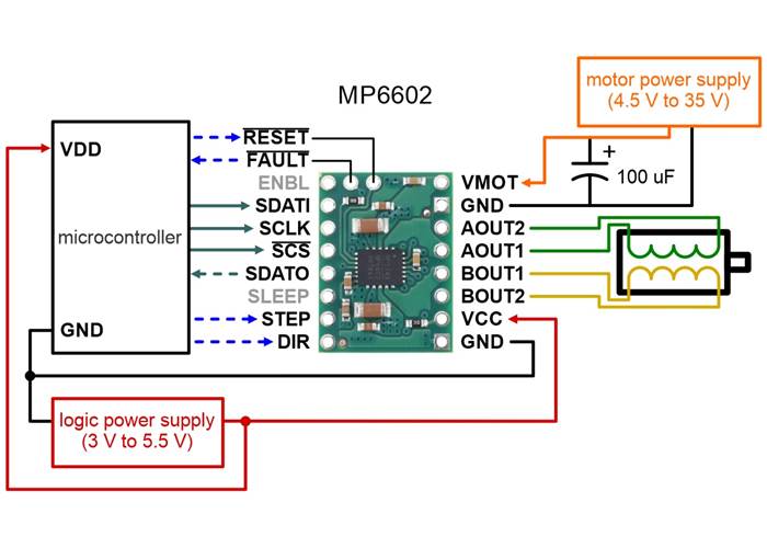
Typical wiring diagram for connecting a microcontroller to the MP6602 Stepper Motor Driver Carrier.
| PIN | Default State | Description |
|---|---|---|
| VMOT | 4.5 V to 35 V motor power supply input. | |
| GND | Ground connection points for the motor and logic supplies. | |
| AOUT1 | Bridge A output terminal 1 (connects to one terminal stepper motor coil A). | |
| AOUT2 | Bridge A output terminal 2 (connects to the other terminal stepper motor coil A). | |
| BOUT1 | Bridge B output terminal 1 (connects to one terminal stepper motor coil B). | |
| BOUT2 | Bridge B output terminal 2 (connects to the other terminal stepper motor coil B). | |
| VCC | 3.0 V to 5.5 V logic power supply input | |
| SCS | pulled high (VCC) | SPI chip selection input (active low) |
| SDATI | pulled low (GND) | SPI data input |
| SDATO | pulled low (GND) | SPI data output |
| SCLK | pulled low (GND) | SPI clock. Data shifts on the rising edge of SCLK |
| SLEEP | pulled low (GND) | Sleep mode input. Pull this pin to logic high to enter low-power sleep mode. |
| ENBL | pulled low (GND) | Enable input. This pin works in conjunction (XOR) with the EN bit in the CTRL register to enable the driver. When the driver is enabled, the outputs are active and the STEP input is recognised. |
| STEP | pulled low (GND) | Step input. A rising edge on this pin advances the motor by one increment. |
| DIR | pulled low (GND) | Direction input. This pin works in conjunction (XOR) with the DIR bit in the CTRL register to set the step direction. |
| FAULT | pulled high (VCC) | Fault indication output. This pin drives low when a fault condition is detected. |
| RESET | pulled high (VCC) | Device reset input. Drive this pin low to reset all registers to their initial states. |
The driver requires a motor supply voltage of 4.5 V to 35 V to be connected across VIN and GND. This supply should be capable of delivering the expected stepper motor current. The VCC pin must also be supplied with the system’s logic voltage.
Four, six, and eight-wire bipolar stepper motors can be driven by the MP6602 if they are properly connected; a FAQ answer explains the proper wirings in detail. A five-wire unipolar stepper motor can also be connected to the MP6602 if it is configured via the SPI interface for unipolar mode. When using it with a unipolar motor, the fifth wire (common terminal) should be connected directly to the motor power supply.
Warning: Connecting or disconnecting a stepper motor while the driver is powered can destroy the driver. (More generally, rewiring anything while it is powered is asking for trouble.)
Stepper motors typically have a step size specification (e.g. 1.8° or 200 steps per revolution), which applies to full steps. A microstepping driver such as the MP6602 allows higher resolutions by allowing intermediate step locations, which are achieved by energizing the coils with intermediate current levels. For instance, driving a motor in quarter-step mode will give the 200-step-per-revolution motor 800 microsteps per revolution by using four different current levels.
The microstep resolution is configured through the SPI interface. For the microstep modes to function correctly, the current limit must be set low enough (see below) so that current limiting gets engaged. Otherwise, the intermediate current levels will not be correctly maintained, and the motor will skip microsteps.
While the MP6602 allows control of a stepper motor through a simple step and direction interface, it should first be enabled and configured through its SPI interface after each power-up. This means that the controlling microcontroller should be capable of acting as an SPI master (either with an SPI peripheral or software SPI), and it must be connected to the SDI, SCLK, and SCS pins. While the SDO and FAULT pins are not required to use this driver, it is generally a good practice to use them to monitor for error conditions.
When the driver is enabled, which can be done through the ENBL input or the SPI interface, the rising edge of each pulse to the STEP input corresponds to one microstep of the stepper motor in the direction selected by the DIR pin (XORed with the DIR bit in the CTRL register). Stepping and direction can also both be controlled solely through SPI, in which case the STEP and DIR pins can be left disconnected.
The MP6602 features an open-drain FAULT output that drives low when a fault condition is detected. The source of the fault can be determined by reading the FAULT and OCP registers through the SPI interface. FAULT is pulled up to VCC on the board, so no external pull-up resistor is needed.
Note: Some fault conditions are latching and must be cleared through the SPI interface or via the RESET pin. See the MP6602 datasheet (1MB pdf) for more information.
The MP6602 has a maximum current rating (and maximum current limit) of 4 A per coil. When the current limit is set to 4 A, the current through both coils will be 2.8A in full-step mode, and it will reach peaks of 4A through one coil (while being 0A in the other) when microstepping. The carrier’s 4-layer, 2oz copper printed circuit board is designed to draw heat out of the IC, and the driver generally did not need any special cooling to supply the full rated current in our tests, but additional cooling might be required for applications that limit heat dissipation, such as use in enclosed spaces or high ambient temperature conditions.
This product can get hot enough to burn you long before the chip overheats. Take care when handling this product and other components connected to it.
The driver’s current limit, which defaults to 1.25 A, is set through its SPI interface. You can confirm you have set it correctly by using a multimeter to measure the actual current through one of the coils while the stepper motor is in full step mode and not stepping. The current you measure this way will be approximately 70% of the set limit. Please note that measuring the current draw at the power supply will generally not provide an accurate measure of the coil current. Since the input voltage to the driver can be significantly higher than the coil voltage, the measured current on the power supply can be quite a bit lower than the coil current (the driver and coil basically act like a switching step-down power supply). Also, if the supply voltage is very high compared to what the motor needs to achieve the set current, the duty cycle will be very low, which also leads to significant differences between average and RMS currents. Additionally, please note that the coil current is a function of the set current limit, but it does not necessarily equal the current limit setting as the actual current through each coil changes with each microstep.
We have written an MP6602 library for Arduino that provides basic functions for configuring and operating the driver using an Arduino or Arduino-compatible controller. The library includes several example sketches.

Schematic diagram of the MP6602 Stepper Motor Driver Carrier.
| Size: | 0.6″ × 0.8″ |
|---|---|
| Weight: | 1.3 g |
| Minimum operating voltage: | 4.5 V |
|---|---|
| Maximum operating voltage: | 35 V |
| Continuous current per phase: | 4 A1 |
| Maximum current per phase: | 4 A |
| Minimum logic voltage: | 3 V |
| Maximum logic voltage: | 5.5 V |
| Microstep resolutions: | full with 70% current, 1/2, 1/4, 1/8, 1/16, 1/32 |
| Current limit control: | SPI |
| Reverse voltage protection?: | N |
| Header pins soldered?: | N |
| PCB dev codes: | md52a |
|---|---|
| Other PCB markings: | 0J16036 |
This application note explains the MP6602’s advanced features (step mode, current limit, automatic hold, off time and blanking time, stall detection, and fault detection) and how to configure the internal registers to use them correctly.
This DXF drawing shows the locations of all of the board’s holes.
This is a library for Arduino that helps interface with an MP6602 stepper motor driver. It uses the Arduino SPI library to communicate with the SPI interface of the MP6602.
Yes. To avoid damaging your stepper motor, you want to avoid exceeding the rated current, which is 600 mA in this instance. All of our stepper motor drivers let you limit the maximum current, so as long as you set the limit below the rated current, you will be within spec for your motor, even if the voltage exceeds the rated voltage. The voltage rating is just the voltage at which each coil draws the rated current, so the coils of your stepper motor will draw 600 mA at 3.9 V. By using a higher voltage along with active current limiting, the current is able to ramp up faster, which lets you achieve higher step rates than you could using the rated voltage.
If you do want to use a lower motor supply voltage for other reasons, consider using our DRV8834 or STSPIN-220 low-voltage stepper motor drivers.
Yes, you do! Setting the current limit on your stepper motor driver carrier is essential to making sure that it runs properly. An appropriate current limit also ensures that your motor is not allowed to draw more current than it or your driver can handle, since that is likely to damage one or both of them.
Setting the current limit on the MP6602 is done through its SPI interface (this is very different from most of our other stepper motor driver carriers, which have their current limits set through their on-board potentiometers). The MP6602 defaults to a current limit of 1.25 A on start-up, which might be more than your stepper motor can safely handle, so we recommend setting current limit to an appropriate value for your stepper motor before enabling the driver outputs to prevent damage to the stepper motor. This is done by through the ISET register. The MP6602 datasheet (1MB pdf) and application note AN189 (1MB pdf) have more information on how to set the current limit through the SPI interface, and our Arduino library includes example sketches showing how to implement this in software.