This tiny carrier board makes it easy to integrate a Sharp GP2Y0D815Z0F, GP2Y0D810Z0F, or GP2Y0D805Z0F digital distance sensor into your project by providing all of the required external components, an LED for feedback about the output state, and a 0.1″-pitch, three-pin interface to the sensor.
Special Order
Shipping from $9.90
+105 more from our supplier in 7-10 days
Our Code: SKU-002511
Supplier Link: [Pololu MPN:1133]
This tiny carrier board makes it easy to integrate a Sharp GP2Y0D815Z0F, GP2Y0D810Z0F, or GP2Y0D805Z0F digital distance sensor into your project by providing all of the required external components, an LED for feedback about the output state, and a 0.1″-pitch, three-pin interface to the sensor.
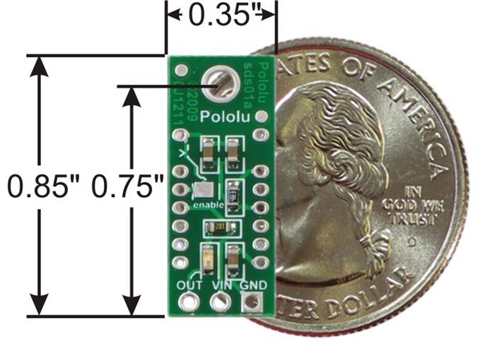
Pololu carrier for Sharp GP2Y0D815Z0F, GP2Y0D810Z0F, and GP2Y0D805Z0F with quarter for size reference.
The GP2Y0D805, GP2Y0D810 , and GP2Y0D815 are Sharp’s smallest and fastest distance sensors, and this tiny carrier board for these sensors includes all of the external components required to make them work. With detection distances up to 150 mm and a typical sampling rate of almost 400 Hz, these sensors provides an attractive alternative to shorter-range LED-phototransistor reflectance pairs and longer-range but slower sensors such as the Sharp GP2Y0A41SK0F analogue distance sensor.
However, these sensors require external components and have a non-standard 1.5 mm pitch, which can make them difficult to integrate into projects based on a 0.1″ pitch. This carrier board includes these components and provides a 0.1″-pitch, three-pin interface: ground, power, and output.
Note: this product requires a Sharp GP2Y0D815Z0F, GP2Y0D810Z0F, or GP2Y0D805Z0F sensor (sold separately). We also offer this carrier board assembled with a GP2Y0D815Z0F, assembled with a GP2Y0D810Z0F, and assembled with a GP2Y0D805Z0F.
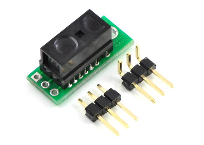
Pololu carrier with Sharp GP2Y0D805Z0F, GP2Y0D810Z0F, or GP2Y0D815Z0F digital distance sensor.
You will need to solder the sensor to the carrier board so that the solder connections are made on the component-side of the board and the sensor package presses against the component-free side of the board. Once the sensor is soldered in, the Pololu carrier board lets you interface with the GP2Y0D815, GP2Y0D810, or GP2Y0D805 sensor using a three-pin 0.1″ connector, such as the included 3×1 straight male header strip and 3×1 right-angle male header strip. You can connect to these pins with a servo cable or with a custom-made cable using pre-crimped wires and a 3×1 crimp connector housing.
The square pad is ground, the middle pad is VIN (2.7 – 6.2 V), and the remaining pad is the sensor output, OUT. Depending on your power source, you might notice an increase in performance by placing a large (>10 uF) capacitor between power and ground somewhere near the sensor.
A red LED on the back of the PCB lights when the output is low, indicating that the sensor is detecting something. If so desired, you can disable this LED by cutting the trace between it and the OUT pin where it is marked on the silkscreen or by desoldering the LED.
The GP2Y0D815Z0F, GP2Y0D810Z0F, and GP2Y0D805Z0F have an optional enable input that can be used to put the sensor into low-power mode. The Pololu carrier board connects this input to Vcc so that the sensor is always enabled, but you can solder a wire to the pad labelled “enable” on the back of the PCB if you want control over this input. Note that you will need to cut the trace that connects the enable line to Vcc on the PCB if you want to be able to disable the sensor. This trace is marked on the silkscreen, and there is a caret that indicates where we suggest you make the cut.
The carrier board has a 0.086″ mounting hole for a #2 or M2 screw. You can make the module more compact by cutting or grinding off this portion of the PCB if you do not need the mounting hole.
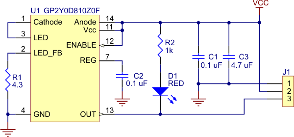 |
Pololu carrier for Sharp GP2Y0D805Z0F, GP2Y0D810Z0F, and GP2Y0D815Z0F sensors schematic diagram. |
|---|
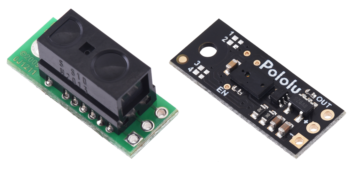
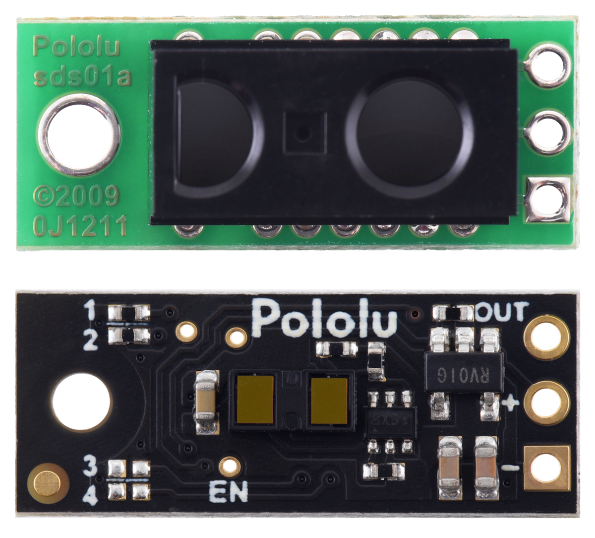
This carrier board is designed for sensors from Sharp/Socle that are no longer in production, so we do not recommend them for new designs where continued availability is important. As an alternative, consider the newer Pololu Digital Distance Sensors, which have the same form factor and pinout as this board.
The Pololu digital distance sensors are available in the same 5 cm, 10 cm, and 15 cm ranges as the Sharp sensors, in addition to longer ranges of up to several meters. This means they can be used as replacements for these older modules, and the longer-range versions can serve as upgrades that provide enhanced detection and measurement capabilities. Also available are versions with pulse-width outputs that can provide quantitative distance measurements instead of simply indicating the presence of an object.
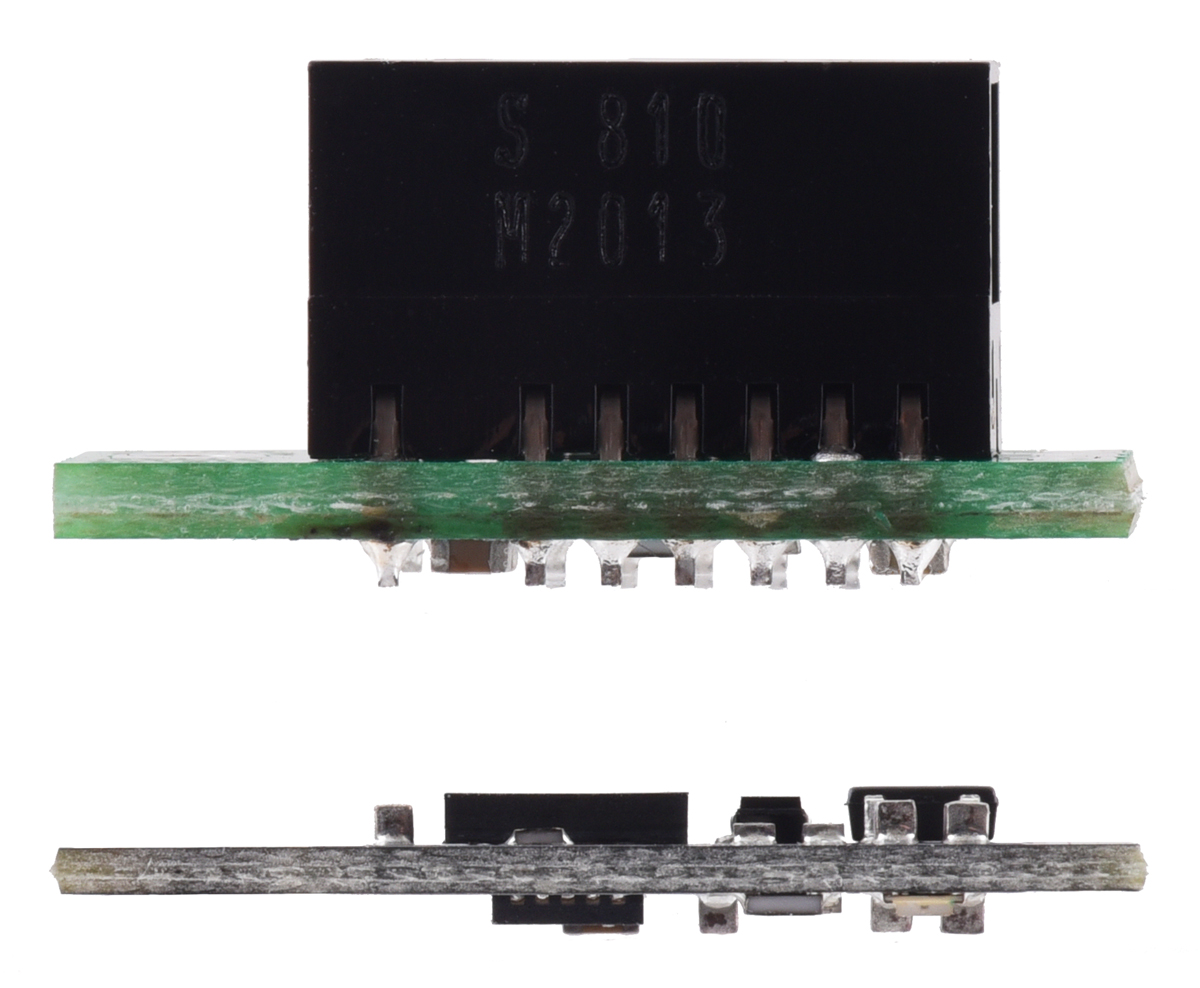
The sensors on these newer units are much thinner than the Sharp modules, so the zero-range point is approximately 7 mm closer to the PCB, and the beam angle of the newer units is wider. The pictures below show side-by-side comparisons of the two:
|
|
|
This DXF drawing shows the locations of all of the board’s holes.