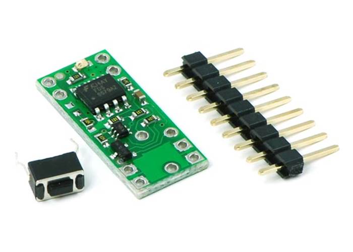
The Pololu Pushbutton Power Switch is a patented design initially created for our Orangutan Robot Controllers as an alternative to bulky mechanical switches. The switch is intended to be the main power switch for a DC device requiring up to several amps of current.
Note: We have released improved versions of these switches in several different power levels and with substantially expanded operating voltage ranges. The new Mini Pushbutton Power Switches are available in an LV version that operates from 2.2 V to 20 V and an SV version that operates from 4.5 V to 40 V. The new Big Pushbutton Power Switches have the same operating range as the Mini SV but offer more current: up to 8 A for the MP version and up to 16 A for the HP version. The new versions also offer reverse voltage protection and more control options. The size and pinout of the new versions are different, as is the amount of current they can deliver, so please check the product pages of the new versions carefully to determine if they can work as a substitute for the old switches in your application.
Once existing stock is gone, these older switches will only be available by large-volume special order. Please contact us for more information.
 |
The Pololu Pushbutton Power Switch is a compact, solid-state power switch controlled by a momentary pushbutton switch. Because the switched current does not flow through the mechanical switch, a large variety of small, low-power switches can be used to control a substantial amount of power. The use of momentary pushbutton switches also allows multiple switches to be used in parallel to control the power to one load. The solid-state switch also allows the load to turn off its own power, which can be beneficial when used with battery chemistries sensitive to over-discharging. Please note that this switch has several drawbacks when compared to mechanical switches, so please be sure you fully understand this product before using it in your system.
The Pololu Pushbutton Power Switch is available in two voltage versions: standard voltage, 4.5-20 V and low voltage, 2.5-7.0 V. Please be sure to select the correct unit for your application. The two versions look very similar, but they can be differentiated by the colour of the LED that illuminates when the switch is on: the SV version has a green LED and the LV version has a red LED.
The Pololu Pushbutton Power Switch works well in its intended application as a DC power switch for small robots, but because it is fundamentally different from a mechanical power switch, the benefits and drawbacks of the components must be fully considered.
Benefits over mechanical switches:
Drawbacks compared to mechanical switches:
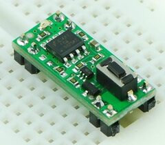 |
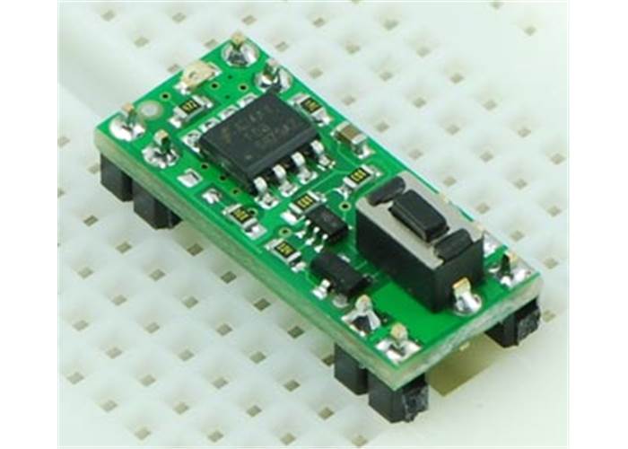
| Pololu Pushbutton Power Switch on a solderless breadboard. |
|---|
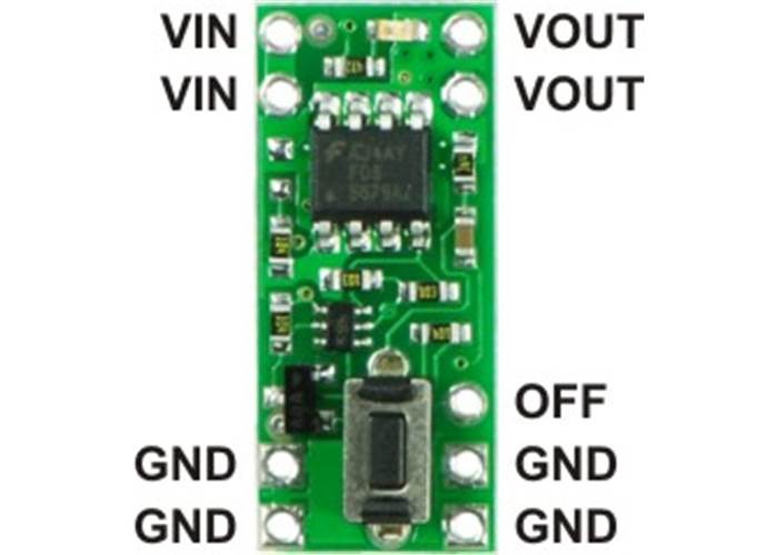
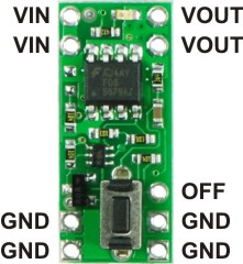
The Pololu Pushbutton Power Switch can fit in an 18-pin DIP (dual in-line package) footprint, making it compatible with solderless breadboards and perforated printed circuit boards with standard 0.1" spacing. For such applications, the included male header pins can be soldered to the switch PCB as shown in the picture to the right. Alternatively, wires can be soldered directly to the switch PCB for non-breadboard applications. For high-current applications, make sure that the wires can safely carry the current. Two pads/pins are provided for each of the power nodes, and multiple pads should be used for applications drawing over 5 A.
The included pushbutton switch can be used to trigger the switch. Alternatively, a separate pushbutton, such as a remote panel-mounted unit, can be used instead. Multiple pushbuttons can be wired in parallel for multiple control points, and each of the parallel pushbuttons will be able to turn the switch on or off. The latching circuit performs some button debouncing, but pushbuttons with excessive bouncing (several ms) might not function well with this product.
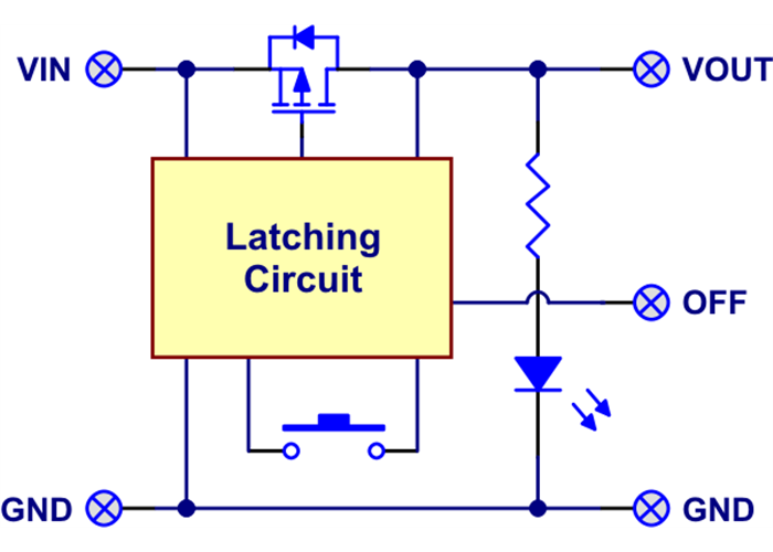
The Pololu Pushbutton Power Switch has two main components: a P-channel power MOSFET that switches the load current and a latching circuit that controls the gate of the MOSFET.

Pololu Pushbutton Power Switch block diagram
The overall switch performance is determined by the MOSFET characteristics, which are specified in their datasheets. The standard voltage version uses the FDS6679AZ (421k pdf); the low-voltage version uses the FDS4465 (141k pdf). The latching circuit is designed to operate over a wide range of voltages and to draw very little current in the off state (typically under 0.01 μA). In the on state, the switch pulls the MOSFET gate to within 0.2 V of ground so that the MOSFET’s Vgs can be approximated as the supply voltage.
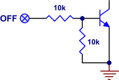 |
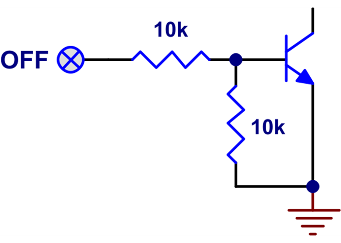
| Pololu Pushbutton Power Switch OFF input detail. |
|---|
The latching circuit controlling the power MOSFET includes an OFF input that can be used by the target device to shut off its own power. The internal structure of this input is shown to the right. Applying more than approximately 1 V to the OFF pin will cause the power switch to turn off. The maximum voltage for the OFF pin is 30 V independent of the switch voltage (VIN).
The switch operating range is limited by the ability to change state reliably. At low voltages, the switch is difficult to turn on, and the switch will turn itself off once the voltage falls far enough (typically 3 V and 1.5 V for the SV and LV versions, respectively). At high voltages, the switches become difficult to turn off. The reliability of turning off is affected by a combination of the supply voltage, the amount of bouncing on the pushbutton switch, and the amount of noise on the supply line. For applications at the high end of the operating range, tests should be performed to ensure that the device can properly turn off.
 Understanding Destructive LC Voltage Spikes (Printable PDF)
Introduction to potentially destructive voltage spikes caused by power lead inductance and low ESR capacitors.