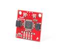
A high-precision IMU breakout featuring the Feyman IM19, designed exclusively for RTK receivers, for precise tilt compensation and PNT sensor fusion.
Special Order
Shipping from $9.90
+5 more from our supplier in 7-10 days
Our Code: SKU-011371
Supplier Link: [SparkFun MPN:30381]
When accuracy is the most important requirement in your PNT projects, standard positioning data often falls short of capturing the full picture. The SparkFun 9DoF IMU Breakout featuring the Feyman (FMI) IM19 is designed to bridge that gap by providing high-precision attitude measurements. It achieves this by combining advanced MEMS sensor data with external GNSS RTK positioning information. Beyond just reporting orientation, this sensor fusion provides more precise tilt compensation, allowing your system to automatically translate the GNSS receiver-reported location from the GNSS antenna position to your actual survey point.
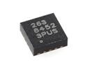
The IM19 is the exact same IMU we trust in SparkPNT's professional-grade GNSS Flex and FP Surveyor products, enabling advanced features such as tilt-compensated surveying and continuous Dead Reckoning navigation.
Because of this reliance on sensor fusion, this IMU is designed to work exclusively with RTK GNSS receivers. To function correctly, it must be fed with GNSS positioning data that actively has an "RTK Fix" status in its NMEA message. This board will not operate with standard, non-RTK GNSS receivers or with positions in "RTK float," "DGPS"/"DGNSS," "3D fix," etc.
When paired with a compatible RTK setup, the IM19 unlocks professional-grade capabilities for your field equipment:
To get started, simply feed the IM19 NMEA GGA, GST, and RMC messages at 5Hz, along with a standard Pulse-Per-Second (PPS) timing signal. The board will then output a proprietary NMEA ASCII GPFMI message containing the compensated position of your survey pole's tip, plus the precise Roll, Pitch, and Yaw of the IMU itself.

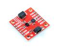
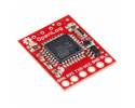
We designed this 9DoF IMU Breakout to be as accessible and modular as possible. It provides flexible access to all three of the IM19's UART interfaces to suit your specific build:
Power management is equally flexible, allowing you to power the board via USB, the 5V VIN pad, or by carefully providing an external 3.3V supply to the 3V3 pads or Pin 1 of the JST connector (which features a configurable 5V jumper).
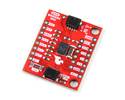
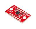
To streamline your physical setup, the 1.7-inch x 1.7-inch PCB matches the footprint of our standard RTK GNSS boards, making it incredibly easy to stack the IM19 directly above or below your existing receiver. Additionally, the IM19 chip is placed exactly at the centre of the board to simplify your physical LEVER_ARM calculations, with a Z-origin of 1.6mm above the top surface (inside the package) and 3.2mm above the bottom surface.
IM19 IMU Breakout
IM19 General Features