This breakout board for the MPS MPQ6612A motor driver offers a wide operating voltage range of 4 V to 40 V and can deliver up to 4 A continuous to a single brushed DC motor.
Special Order
Shipping from $4.90
+83 more from our supplier in 7-10 days
Our Code: SKU-011336
Supplier Link: [Pololu MPN:5286]
This breakout board for the MPS MPQ6612A motor driver offers a wide operating voltage range of 4 V to 40 V and can deliver up to 4 A continuous to a single brushed DC motor. The MPQ6612A has built-in current sensing and regulation that limits the peak motor current to 7.5 A by default, as well as protection against over-current and over-temperature. The carrier board also adds reverse-voltage protection. This version includes soldered connectors, so no soldering is required to use it.
This product is a carrier board for the Monolithic Power Systems (MPS) MPQ6612A brushed DC motor driver; we therefore recommend careful reading of the MPQ6612A datasheet (573k pdf).
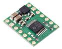
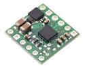
MPQ6612A Single Brushed DC Motor Driver Carrier (Soldered Connectors). (1) |
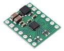
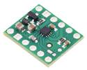
MPQ6612A Single Brushed DC Motor Driver Carrier (Soldered Connectors), bottom view. |
The MPQ6612A is an H-bridge motor driver IC that can be used for bidirectional control of one brushed DC motor with a supply range of 4 V to 40 V. It can deliver up to approximately 4 A continuous on our carrier board and features configurable current sensing and current limiting. The board ships populated with all of its SMD components, including the MPQ6612A.
This version includes soldered connectors, so no soldering is required to use it. We also have a version without connectors that allows for different assembly options.
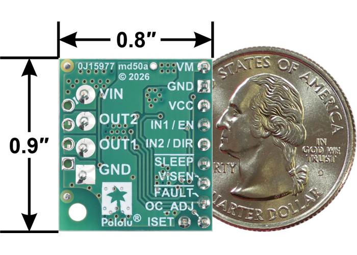
MPQ6612A Single Brushed DC Motor Driver Carrier (Soldered Connectors), bottom view with dimensions and a US quarter for size reference.
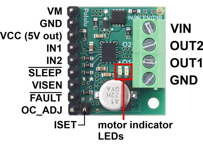
Pinout of the MPQ6612A Single Brushed DC Motor Driver Carrier (Soldered Connectors).
| PIN | Default State | Description |
|---|---|---|
| VIN | 4 V to 40 V board power supply input. | |
| GND | Ground connection points for the motor and logic supplies. | |
| OUT1 | Motor output 1 (connects to one terminal of a DC motor). | |
| OUT2 | Motor output 2 (connects to the other terminal of a DC motor). | |
| VM | This pin gives access to the motor power supply after the reverse-voltage protection MOSFET (see the board schematic below). It can be used to supply reverse-protected power to other components in the system. | |
| VCC | This pin gives access to the 5V output from the driver IC’s internal LDO regulator, which can be useful as a reference or for powering small external circuits. This output should not be connected to other external power supply lines. VCC will output 5 V for VIN > 5.2 V; otherwise, VCC will output VIN − 0.2 V. Note: this output is disabled when sleep mode is active, so it cannot be used to pull up SLEEP. | |
| IN1 | LOW (200 kΩ pull-down) |
Control input 1. PWM can be applied to this pin. |
| IN2 | LOW (200 kΩ pull-down) |
Control input 2. PWM can be applied to this pin. |
| SLEEP | LOW (500 kΩ pull-down) |
Sleep input that puts the MPQ6612A into a low-power sleep mode when low. This pin must be set high to enable the driver. |
| VISEN | Current sense output. This pin provides an analogue current-sense feedback voltage of 200 mV/A by default (see below). | |
| FAULT | FLOATING | Open-drain fault output that is pulled low under whenever the MPQ6612A protection circuits are active (e.g. during over-current, over-temperature, or over-voltage conditions) and floating otherwise. To use this output, externally pull this pin up to your system’s logic voltage. |
| OC_ADJ | FLOATING | Over-current (OC) threshold programming pin. Leaving it floating sets the OC threshold to between 9 A and 19 A (13 A typical) while grounding this pin sets the OC threshold to between 13 A and 25 A (19 A typical). |
| ISET | 2 kΩ resistor to GND | Current sensing and current limiting configuration pin. A 2 kΩ resistor is connected from this pin to ground, which results in a current sense sensitivity of 200 mV/A and a current limiting threshold of 7.5 A (see below for more info). |
We manufacture these boards in-house at our Las Vegas facility, so we can make these motor drivers with customised components to better meet the needs of your project, such as by customising the ISET pull-down resistor, which sets the current limit and current sense sensitivity. If you are interested in customisation, please contact us.
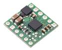
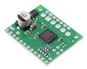
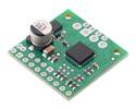
The motor and motor power (4 V to 40 V) connections are accessed through a 4-pin, 3.5mm-pitch terminal block on one side of the board, and the control connections (1.5 V to 5 V logic) are accessed through 0.1″-pitch male headers on the other side. on the other. For alternative connector arrangements, we have a version of this carrier available without connectors as shown in the right picture below.
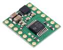
MPQ6612A Single Brushed DC Motor Driver Carrier (Soldered Connectors). |
|
The driver is disabled by default, and enabling it requires setting SLEEP high. This can be done through general purpose digital outputs from the controlling device, which allows for dynamic control of these enable modes, or by pulling the pin up to a voltage rail between 1.5 V and 5.5 V. Note that the driver’s 5 V output (VCC) cannot be used for pulling up SLEEP as VCC is disabled while the driver is in sleep mode.
This board features motor indicator LEDs that can be used to test that motor driver outputs are working as expected before actually connecting a motor (this can be especially helpful in detecting problems due to insufficient power supplies). The LED brightness increases with motor speed, and the LED colour changes with direction.
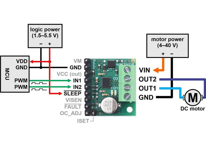
Minimal wiring diagram for connecting a microcontroller to a MPQ6612A Single Brushed DC Motor Driver Carrier (Soldered Connectors).
Aside from motor and power connections (including a logic voltage connection to SLEEP), the only required control pins are IN1 and IN2. The following simplified truth table shows how these two control pins affect the driver outputs:
| IN1 | IN2 | OUT1 | OUT2 | operating mode |
|---|---|---|---|---|
| 0 | 0 | Z | Z | coast (outputs off) |
| PWM | 0 | PWM (H/Z) | PWM (L/Z) | forward/coast at speed PWM % |
| 0 | PWM | PWM (L/Z) | PWM (H/Z) | reverse/coast at speed PWM % |
| PWM | 1 | L | PWM (L/H) | reverse/brake at speed 100% − PWM % |
| 1 | PWM | PWM (L/H) | L | forward/brake at speed 100% − PWM % |
| 1 | 1 | L | L | brake low (outputs shorted to ground) |
The MPQ6612A can sense the motor current and actively limit it by using constant-off-time PWM current regulation (current chopping). The feedback sensitivity and current limiting threshold are set by a resistance connected between the ISET pin and ground. The carrier board is populated with a 2 kΩ pull-down resistor on ISET, which makes the VISEN pin output a voltage of 200 mV/A and limits the current to 7.5 A by default. This behaviour can be customised by adding an external pull-down resistor to the ISET pin in parallel with the one already on the carrier. This will reduce the overall resistance, increasing the current limit and decreasing the VISEN sensitivity. Connecting ISET directly to GND disables current limiting (and current sensing). To reduce the current limit and increase the VISEN sensitivity, the on-board 2 kΩ surface mount resistor would need to be removed and replaced with a surface mount or external resistor of a larger value. Refer to the MPQ6612A datasheet for more information about the driver’s current sensing and current limiting.
The MPQ6612A is rated for a maximum continuous current of 5 A, which typically requires extra airflow or heat sinking to achieve. The actual current you can deliver will depend on how well you can keep the motor driver cool, and the carrier’s printed circuit board is designed to help with this by drawing heat out of the motor driver chip. On our carrier board at room temperature and with no forced air flow, the chip is able to deliver 5 A for between 30 seconds and a few minutes before activating the chip’s thermal protection; a continuous current of 4 A is typically sustainable for many minutes without triggering a thermal shutdown. At the board’s default current limit of 7.5 A, thermal shutdown occurs within a few seconds.
This product can get hot enough to burn you long before the chip overheats. Take care when handling this product and other components connected to it.

Schematic diagram of the MPQ6612A Single Brushed DC Motor Driver Carrier.
| Size: | 0.8″ × 0.9″ × 0.5″ |
|---|---|
| Weight: | 4.5 g |
| Motor driver: | MPQ6612A |
|---|---|
| Motor channels: | 1 |
| Minimum operating voltage: | 4 V |
| Maximum operating voltage: | 40 V |
| Continuous output current per channel: | 4 A |
| Peak output current per channel: | 7.5 A1 |
| Current sense: | 0.2 V/A2 |
| Maximum PWM frequency: | 200 kHz |
| Minimum logic voltage: | 1.5 V |
| Maximum logic voltage: | 5.5 V3 |
| Reverse voltage protection?: | Y |
| Connectors?: | Y |
| PCB dev codes: | md50a |
|---|---|
| Other PCB markings: | 0J15977 |
This DXF drawing shows the locations of all of the board’s holes.