voltage stroke length weight limit switches feedback 12 V 100 mm 59 g gearbox max dynamic load performance @12 V no load max load 100:1 4.3 kgf 17.6 mm/s, 150 mA 11.6 mm/s, 310 mA
Special Order
Shipping from $9.90
+18 more from our supplier in 7-10 days
Our Code: SKU-011315
Supplier Link: [Pololu MPN:4487]
| voltage | stroke length | weight | limit switches | feedback |
|---|---|---|---|---|
| 12 V | 100 mm | 59 g |
| gearbox | max dynamic load |
performance @12 V | |
|---|---|---|---|
| no load | max load | ||
| 100:1 | 4.3 kgf | 17.6 mm/s, 150 mA | 11.6 mm/s, 310 mA |
The Glideforce GF01 series is a set of micro-sized linear actuators from Concentric International weighing between 30 g and 60 g, depending on the stroke length. They consist of small 12V DC gearmotors that drive a lead screw to move a shaft back and forth, turning the rotational motion of the motor into linear motion of the shaft. The shaft will hold its position even when unpowered and subjected to static loads up to 4 kgf [9 lb or 40 N]. The actuators have an aluminium extension tube and inner tube with a plastic case and end-cap, and the entire case is sealed to protect against dust and water (rated IP66).
The GF01 series of actuators are available either with an integrated feedback potentiometer that lets you determine where the actuator is in its stroke, which can be used for closed-loop position control, or with two preset limit switches that safely stop the motor at either end of its range while still allowing it to reverse direction if the supplied voltage is reversed.

Glideforce Micro (GF01) series of linear actuators.
These actuators are available in several gear ratios and a variety of stroke lengths, from 10 mm to 100 mm. The comparison table below shows all of the micro-sized linear actuators we carry:
| Actuator Type |
Max Dynamic Load |
No-Load Speed @ 12 V |
Max-Load Speed @ 12 V |
Current Draw @ 12 V |
Weight | Nominal Stroke Length |
With Feedback (no limit switches) |
With Limit Switches (no feedback) |
|
|---|---|---|---|---|---|---|---|---|---|
| Micro(GF01) 50:1 | 2.2 kgf [4.9 lb] |
2.8 cm/s [1.1″/s] |
2.1 cm/s [0.8″/s] |
0.15 A – 0.4 A |
31 g | 1 cm | (0.39″) | — | GF01-120501-1-66 |
| 37 g | 3 cm | (1.2″) | — | GF01-120503-1-66 | |||||
| 42 g | 5 cm | (2.0″) | — | GF01-120505-1-66 | |||||
| 57 g | 10 cm | (3.9″) | — | GF01-120510-1-66 | |||||
| Micro(GF01) 100:1 | 4.3 kgf [9.4 lb] |
1.8 cm/s [0.7″/s] |
1.2 cm/s [0.5″/s] |
0.15 A – 0.3 A |
31 g | 1 cm | (0.39″) | — | GF01-121001-1-66 |
| 39 g | 3 cm | (1.2″) | GF01-121003-2-66 | GF01-121003-1-66 | |||||
| 44 g | 5 cm | (2.0″) | GF01-121005-2-66 | GF01-121005-1-66 | |||||
| 59 g | 10 cm | (3.9″) | GF01-121010-2-66 | GF01-121010-1-66 | |||||
| Micro(GF01) 210:1 | 8.1 kgf [18 lb] |
0.9 cm/s [0.3″/s] |
0.6 cm/s [0.2″/s] |
0.15 A – 0.25 A |
31 g | 1 cm | (0.39″) | — | GF01-122101-1-66 |
| 39 g | 3 cm | (1.2″) | GF01-122103-2-66 | GF01-122103-1-66 | |||||
| 44 g | 5 cm | (2.0″) | GF01-122105-2-66 | GF01-122105-1-66 | |||||
| 59 g | 10 cm | (3.9″) | GF01-122110-2-66 | GF01-122110-1-66 | |||||

Glideforce GF01 Micro Linear Actuator, 100mm stroke.
Warning: This actuator does not have any limit switches to automatically deenergize the motor at either end of the stroke, so extreme care must be taken to prevent the actuator from running into the physical ends of the stroke. Otherwise, the actuator could be permanently damaged. Please refer to the GF01 datasheet (1MB pdf) for detailed information about the potentiometer feedback.
The following specifications apply to all Glideforce GF01 series linear actuators:
For more details, see the GF01 Linear Actuator Datasheet (1MB pdf).
Diagrams of the linear actuators are shown below. For more detailed information, including the retracted and extended lengths of each version, see the datasheet.

Dimensions of Glideforce GF01 micro series linear actuators. Units are mm.
The GF01 actuators have a 300 mm (12″) cable with unterminated, stripped leads. The actuators with feedback have five leads while the ones with limit switches have two, as shown in the pictures below.
|
Unterminated wire ends for Glideforce GF01 micro linear actuators with feedback. |
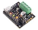
To drive the actuator, simply connect a power source of up to 12 V to the red and black motor leads. Reversing the applied voltage will reverse the direction of motion. A motor controller or motor driver is required for electronic speed and direction control. We recommend our Jrk G2 21v3 motor controllers for use with the feedback actuators (see below for more information on this) and our Motoron motor controllers for controlling the actuators without feedback, though many of our other motor controllers and motor drivers are capable of powering these actuators.
Warning: The GF01 actuator versions with feedback potentiometers do not have internal limit switches to automatically deenergize the motor at either end of the stroke, so extreme care must be taken with these versions to prevent the actuator from running into the physical ends of the stroke. Otherwise, the actuator could be permanently damaged. These versions should only be used with feedback-based control that is set up to prevent the actuator from driving past the feedback thresholds at the limits of its range.
 |
Connecting a micro linear actuator with feedback to a Jrk 21v3 motor controller. |
|---|
The feedback features of our Jrk G2 21v3 motor controller (which is also available with connectors soldered) make it a great solution for precisely controlling our linear actuators with feedback. Our settings file for the Jrk G2 configuration utility makes setup easy, eliminating the need to tune the PID constants. To get started, follow the steps below:
 |
Glideforce linear actuators, from left to right: 6″ Industrial Duty (ID), 6″ Medium Duty (MD), 6″ Light Duty (LD), 50 mm Micro. |
|---|
We carry a variety of Glideforce linear actuators, from the Micro GF01 series, which weigh under 60 g, through the industrial-duty ID series, which can withstand dynamic loads up to 1000 lb. The table below shows our full offering of these linear actuators, sorted by increasing dynamic load capabilities:
| Actuator Type |
Max Dynamic Load |
No-Load Speed @ 12 V |
Max-Load Speed @ 12 V |
Current Draw @ 12 V |
Weight | Nominal Stroke Length |
With Feedback (no limit switches) |
With Limit Switches (no feedback) |
||
|---|---|---|---|---|---|---|---|---|---|---|
| Micro(GF01) 50:1 | 2.2 kgf [4.9 lb] |
2.8 cm/s [1.1″/s] |
2.1 cm/s [0.8″/s] |
0.15 A – 0.4 A |
31 g | 1 cm | (0.39″) | — | GF01-120501-1-66 | |
| 37 g | 3 cm | (1.2″) | — | GF01-120503-1-66 | ||||||
| 42 g | 5 cm | (2.0″) | — | GF01-120505-1-66 | ||||||
| 57 g | 10 cm | (3.9″) | — | GF01-120510-1-66 | ||||||
| Micro(GF01) 100:1 | 4.3 kgf [9.4 lb] |
1.8 cm/s [0.7″/s] |
1.2 cm/s [0.5″/s] |
0.15 A – 0.3 A |
31 g | 1 cm | (0.39″) | — | GF01-121001-1-66 | |
| 39 g | 3 cm | (1.2″) | GF01-121003-2-66 | GF01-121003-1-66 | ||||||
| 44 g | 5 cm | (2.0″) | GF01-121005-2-66 | GF01-121005-1-66 | ||||||
| 59 g | 10 cm | (3.9″) | GF01-121010-2-66 | GF01-121010-1-66 | ||||||
| Micro(GF01) 210:1 | 8.1 kgf [18 lb] |
0.9 cm/s [0.3″/s] |
0.6 cm/s [0.2″/s] |
0.15 A – 0.25 A |
31 g | 1 cm | (0.39″) | — | GF01-122101-1-66 | |
| 39 g | 3 cm | (1.2″) | GF01-122103-2-66 | GF01-122103-1-66 | ||||||
| 44 g | 5 cm | (2.0″) | GF01-122105-2-66 | GF01-122105-1-66 | ||||||
| 59 g | 10 cm | (3.9″) | GF01-122110-2-66 | GF01-122110-1-66 | ||||||
| Actuator Type |
Max Dynamic Load |
No-Load Speed @ 12 V |
Max-Load Speed @ 12 V |
Current Draw @ 12 V |
Weight | Nominal Stroke Length |
With Feedback |
Without Feedback |
||
| High-SpeedLight-Duty(LD) 5:1 | 12 kgf [27 lb] |
8.4 cm/s [3.3″/s] |
7.5 cm/s [2.9″/s] |
1.1 A – 3.4 A |
1.1 kg | 2″ | (5 cm) | GF23-120502-3-65 | GF23-120502-1-65 | |
| 1.2 kg | 4″ | (10 cm) | GF23-120504-3-65 | GF23-120504-1-65 | ||||||
| 1.3 kg | 6″ | (15 cm) | GF23-120506-3-65 | GF23-120506-1-65 | ||||||
| 1.3 kg | 8″ | (20 cm) | GF23-120508-3-65 | GF23-120508-1-65 | ||||||
| 1.4 kg | 10″ | (25 cm) | GF23-120510-3-65 | GF23-120510-1-65 | ||||||
| 1.5 kg | 12″ | (30 cm) | GF23-120512-3-65 | GF23-120512-1-65 | ||||||
| Light-Duty(LD) 5:1 | 15 kgf [34 lb] |
4.4 cm/s [1.7″/s] |
3.6 cm/s [1.4″/s] |
1.2 A – 3.2 A |
1.1 kg | 2″ | (5 cm) | LACT2P-12V-05 | LACT2-12V-05 | |
| 1.2 kg | 4″ | (10 cm) | LACT4P-12V-05 | LACT4-12V-05 | ||||||
| 1.3 kg | 6″ | (15 cm) | LACT6P-12V-05 | LACT6-12V-05 | ||||||
| 1.3 kg | 8″ | (20 cm) | LACT8P-12V-05 | LACT8-12V-05 | ||||||
| 1.4 kg | 10″ | (25 cm) | LACT10P-12V-05 | LACT10-12V-05 | ||||||
| 1.5 kg | 12″ | (30 cm) | LACT12P-12V-05 | LACT12-12V-05 | ||||||
| Light-Duty(LD) 10:1 | 25 kgf [55 lb] |
2.8 cm/s [1.1″/s] |
2.3 cm/s [0.9″/s] |
1.2 A – 3.2 A |
1.1 kg | 2″ | (5 cm) | LACT2P-12V-10 | LACT2-12V-10 | |
| 1.2 kg | 4″ | (10 cm) | LACT4P-12V-10 | LACT4-12V-10 | ||||||
| 1.3 kg | 6″ | (15 cm) | LACT6P-12V-10 | LACT6-12V-10 | ||||||
| 1.3 kg | 8″ | (20 cm) | LACT8P-12V-10 | LACT8-12V-10 | ||||||
| 1.4 kg | 10″ | (25 cm) | LACT10P-12V-10 | LACT10-12V-10 | ||||||
| 1.5 kg | 12″ | (30 cm) | LACT12P-12V-10 | LACT12-12V-10 | ||||||
| Light-Duty(LD) 20:1 | 50 kgf [110 lb] |
1.5 cm/s [0.57″/s] |
1.2 cm/s [0.48″/s] |
1.2 A – 3.2 A |
1.1 kg | 2″ | (5 cm) | LACT2P-12V-20 | LACT2-12V-20 | |
| 1.2 kg | 4″ | (10 cm) | LACT4P-12V-20 | LACT4-12V-20 | ||||||
| 1.3 kg | 6″ | (15 cm) | LACT6P-12V-20 | LACT6-12V-20 | ||||||
| 1.3 kg | 8″ | (20 cm) | LACT8P-12V-20 | LACT8-12V-20 | ||||||
| 1.4 kg | 10″ | (25 cm) | LACT10P-12V-20 | LACT10-12V-20 | ||||||
| 1.5 kg | 12″ | (30 cm) | LACT12P-12V-20 | LACT12-12V-20 | ||||||
| Actuator Type |
Max Dynamic Load |
No-Load Speed @ 12 V |
Max-Load Speed @ 12 V |
Current Draw @ 12 V |
Weight | Nominal Stroke Length |
With Feedback |
Without Feedback |
||
| Medium-Duty (MD) |
100 kgf [225 lb] |
1.5 cm/s [0.58″/s] |
1.0 cm/s [0.41″/s] |
1.1 A – 4.6 A |
1.1 kg | 4″ | (10 cm) | MD122004-P | MD122004 | |
| 1.2 kg | 6″ | (15 cm) | MD122006-P | MD122006 | ||||||
| 1.3 kg | 8″ | (20 cm) | MD122008-P | MD122008 | ||||||
| 1.4 kg | 10″ | (25 cm) | MD122010-P | MD122010 | ||||||
| 1.5 kg | 12″ | (30 cm) | MD122012-P | MD122012 | ||||||
| Actuator Type |
Max Dynamic Load |
No-Load Speed @ 12 V |
Max-Load Speed @ 12 V |
Current Draw @ 12 V |
Weight | Nominal Stroke Length |
With Feedback |
Without Feedback |
||
| Industrial-Duty (ID) with Acme screw drive |
250 kgf [550 lb] |
1.7 cm/s [0.66″/s] |
1.4 cm/s [0.56″/s] |
2.4 A – 13.2 A |
4.2 kg | 4″ | (10 cm) | LACT4-500APL | LACT4-500AL | |
| 4.4 kg | 6″ | (15 cm) | LACT6-500APL | LACT6-500AL | ||||||
| 4.7 kg | 8″ | (20 cm) | LACT8-500APL | LACT8-500AL | ||||||
| 5.3 kg | 12″ | (30 cm) | LACT12-500APL | LACT12-500AL | ||||||
| 6.0 kg | 18″ | (45 cm) | LACT18-500APL | LACT18-500AL | ||||||
| 7.0 kg | 24″ | (60 cm) | LACT24-500APL | LACT24-500AL | ||||||
| Industrial-Duty (ID) with ball screw drive |
450 kgf [1000 lb] |
1.7 cm/s [0.66″/s] |
1.4 cm/s [0.56″/s] |
2.4 A – 13.2 A |
4.6 kg | 4″ | (10 cm) | LACT4-1000BPL | LACT4-1000BL | |
| 4.9 kg | 6″ | (15 cm) | LACT6-1000BPL | LACT6-1000BL | ||||||
| 5.1 kg | 8″ | (20 cm) | LACT8-1000BPL | LACT8-1000BL | ||||||
| 5.6 kg | 12″ | (30 cm) | LACT12-1000BPL | LACT12-1000BL | ||||||
| 6.5 kg | 18″ | (45 cm) | LACT18-1000BPL | LACT18-1000BL | ||||||
| 7.4 kg | 24″ | (60 cm) | LACT24-1000BPL | LACT24-1000BL | ||||||
| Actual stroke length: | 100 mm |
|---|---|
| Retracted length: | 157 mm |
| Extended length: | 257 mm |
| Weight: | 59 g |
| Gear ratio: | 100:1 |
|---|---|
| Current @ 12V, no load: | 150 mA |
| Current @ 12V, max load: | 310 mA |
| Stall current @ 12V: | 350 mA1 |
| Linear speed @ 12V, no load: | 17.6 mm/s |
| Linear speed @ 12V, max load: | 11.6 mm/s |
| Max linear force @ 12V: | 9.4 lb2 |
| Maximum duty cycle: | 20 |
| Feedback potentiometer included?: | Y |
| Limit switches included?: | N |
| Minimum operating temperature: | -10 °C |
| Maximum operating temperature: | 50 °C |
| IP rating: | 66 |
This file contains 3D models (in the step file format) of the Glideforce GF01 Micro Linear Actuators.