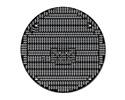
This kit gives you everything you need to add a second level to your 3pi robot. In this version, the LCD pins are brought up to the expansion board from the base via extended headers for your own custom use. This red printed circuit board can also serve as a general-purpose round prototyping board.
Special Order
Shipping from $7.90
+28 more from our supplier in 7-10 days
Our Code: SKU-002450
Supplier Link: [Pololu MPN:976]
This kit includes a round printed circuit board (PCB) with holes spaced on a 0.100" grid, two extended 2×7 male headers, two extended 1×2 male headers, one 2×7 female header, two 1×2 female headers, four 7/8" nylon spacers, four 1-1/4" screws, and four nuts.

Hardware included with the 3pi expansion kit without cutouts
The expansion PCB matches the diameter of the 3pi chassis and mounts just above the tops of the wheels using the four included screws and spacers. Once assembled, the PCB has electrical connections to the base that allow you interface your own electronics with the 3pi robot, which is sold separately. These connections give you access to the ATmega168’s LCD pins, ISP programming pins, and free/jumpered pins, as well as to the three on-board voltages: VBAT (battery voltage), VCC (regulated 5 V), and VBST (regulated 9.25 V that is supplied to the motors). Additionally, the expansion PCB connects to the base’s power button and battery charge port, allowing you to add your own power buttons and charge ports.
Note: This expansion kit replaces the 3pi’s LCD. If you want to preserve the LCD, please consider the version of the expansion kit with cutouts or the more advanced m3pi expansion kit.
This version of the kit might be preferable over the version with cutouts to those who want additional I/O lines or extra prototyping space and do not need the LCD. A wireless module, for instance, might need the I/O and make the on-board LCD unnecessary if data is relayed to a nearby PC. For a more advanced expansion kit, please consider the m3pi expansion kit, which lets you turn your 3pi robot into an m3pi robot.

3pi expansion kit without cutouts mounted on a 3pi robot (black solder mask version)
The expansion PCB is designed to provide plenty of prototyping space for your components. It has room for two 0.6" 40-pin DIP (dual in-line package) components, such as the ATmega32 in the picture below, or for numerous smaller DIP components. The prototyping space extends all the way to the edge of the PCB, allowing you convenient points to mount a variety of sensors such as bumper switches and range-finders. The silkscreen shows how the pads are connected; the electrical connections are on the bottom side. You can cut the copper traces on that bottom side (with a sharp knife or a small rotary tool cutoff wheel) if some of the pre-made connections interfere with your desired layout.

3pi expansion kit (without cutouts) PCB populated with various components (black solder mask version)
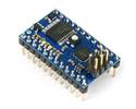
Two of the unused I/O lines on the 3pi’s microcontroller are its serial transmit and receive lines. This means that you can add a second microcontroller or microcontroller board, such as a Baby Orangutan, Basic Stamp, or Arduino Nano, to the expansion PCB. This second microcontroller would deal with all of the sensors and additional hardware on the expansion PCB and control the base via serial commands. We have released a serial slave program for the 3pi base that turns it into a serially controlled platform that can be driven at the whim of another microcontroller.
The supplied header pins allow you to establish all of the necessary electrical connections between the expansion PCB and the 3pi base. We recommend that you fully assemble the 3pi and its expansion kit before you solder anything. This will ensure that once everything is soldered in, the expansion platform will align properly with the base. We suggest that you assemble your expansion kit in the following order:
1) Place the 2×7 female header and one of the 2×1 female headers into the proper holes in the 3pi base as shown below (see the yellow rectangles).

Pololu 3pi robot with expansion kit female headers marked by yellow rectangles
2) Insert the long ends of one 2×7 and one 2×1 extended male header into these female headers, and insert an extended 2×1 male header into the battery charge port. Lastly, remove the LCD and insert an extended 2×7 male header into the LCD port. Place the expansion PCB so the tops of these male headers seat in the proper places, as marked by the rectangles in the picture below. Note that the expansion PCB mounts with the silkscreen facing up.

Solder connections for male headers on the 3pi expansion kit without cutouts
3) Slip a nylon spacer between the base and the expansion PCB so that it lines up with the mounting hole on the base. Insert a screw from the underside of the base up through the base’s mounting hole, the spacer, and the mounting hole on the expansion board. Holding the head of the screw against the base, twist the nut onto the other side, but don’t tighten it all the way. Repeat this process for the three remaining screws, and then tighten them together so that the expansion PCB is aligned well with the base.
4) With the screws holding everything in place, you can now solder the female headers to the base and the male headers to the expansion PCB. Once everything is soldered in, you can remove the screws and pull the expansion PCB off of the base; it should look like the one in the picture below.

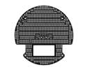
Bottom view of 3pi expansion kit without cutouts (black solder mask version)
After assembly you will have a single 2×1 female header left over. You can use this to create your own battery charge port on the expansion PCB.
Note: This product is a kit designed to augment the 3pi robot (sold separately). Assembly of this kit requires soldering.
| Colour: | red |
|---|
Yes. The easiest way to augment your 3pi is through an expansion kit, which can comes either with cutouts that let you see the LCD below or without cutouts. The version without cutouts replaces the LCD, giving you access to more I/O lines and more prototyping space. An expansion kit is not required for addition of your own electronics, however.
The 3pi robot has a limited number of free I/O lines that can be used as inputs for additional sensors or to control additional electronics such as LEDs or servos. Please see section 10.c of the 3pi user’s guide for more information.
Because the 5 V goes through two power stages, the answer is not completely clear-cut. The 5 V regulator itself has a 900 mW power dissipation limit, so with a 4.3 V drop from the 9.3 V boost voltage to 5 V, we get just over 200 mA. The stock electronics on the 3pi typically use under 50 mA (however, this depends on what your program is doing, if you are making high-frequency noise with the buzzer, and so on), so you could figure an absolute max of 150 mA, with 100 mA being a more comfortable guideline.
However, the boost voltage has a limit of its own of around 1 A, which is dependent on your battery voltage. The motors and IR LEDs also use this supply, so using a lot for your 5 V will affect what is available for the motors. You can almost stall the motors and still have the full boost voltage on the motors in the stock configuration; if you’re also drawing an extra 200 mA for other electronics, the boost voltage will start dropping as the motors approach stall, though this is not necessarily a bad thing since it will limit the stress on the motors and lower the voltage drop on the linear regulator.