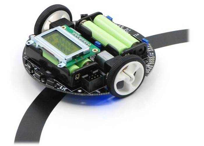
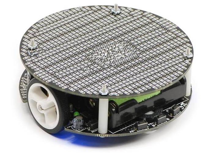
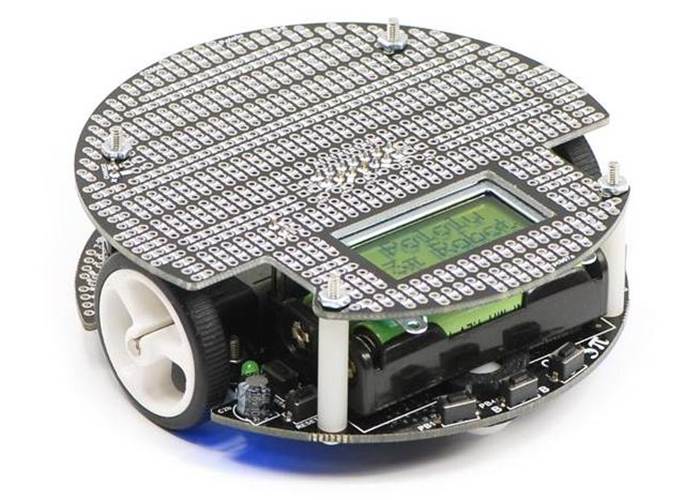
The Pololu 3pi robot is a complete, assembled, high-performance mobile platform featuring two gearmotors, five reflectance sensors, an 8×2 character LCD, a buzzer, and three user pushbuttons, all connected to an ATmega328 microcontroller. A great first robot for ambitious beginners or a ready made platform for experienced enthusiasts. Check out the videos!
In stock in Australia
Shipping from $7.90
Our Code: KIT-70001
Supplier Link: [Pololu MPN:975]
The Arduino compatible Pololu 3pi robot is an excellent platform with so many features built in while allowing hacking and modification ( == fun) due to its ATmega328 processor, optional expansion kit and built in regulated power supply. The 3pi robot is designed to excel in line-following and maze-solving competitions. Plus it's really quick at 1 meter/second - see the videos below.
...the 3pi has been more thoroughly field tested than any other robot we’ve worked with. We’ve had way too much fun with this little robot and by the time you finish reading the review, you’ll probably want to buy one or two for yourself.
R. Steven Rainwater, robots.net
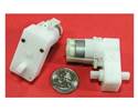
The 3pi has a small size (9.5 cm/3.7" diameter, 83 g/2.9 oz without batteries). For the nerdy, 3 x 3.1415 ≈ 9.5cm. It takes just four AAA cells (not included), while a unique power system runs the motors at a constant 9.25 V independent of the battery charge level. The regulated voltage allows the 3pi to reach speeds up to 100 cm/second while making precise turns and spins that don’t vary with the battery voltage.
The 3pi robot makes a great platform for people with C programming experience to learn robotics, and it is a fun environment for ambitious beginners to learn C programming. If you have any programming experience, particularly in C# or Java the leap back to C is easy enough.
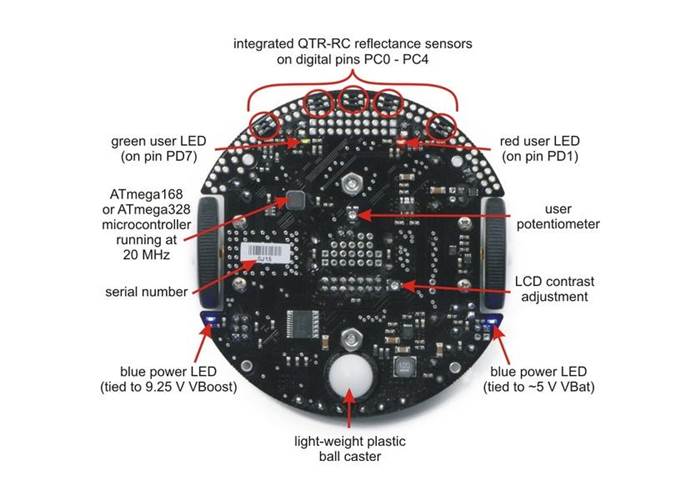
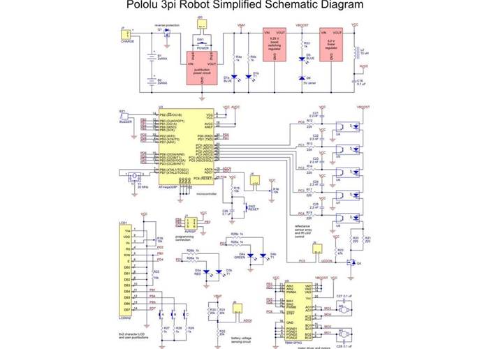
At its heart is an Atmel ATmega328P microcontroller running at 20 MHz. The 3pi robots feature 32 KB of flash program memory, 2 KB RAM, and 1 KB of persistent EEPROM memory. The popular, free GNU C/C++ compiler works perfectly with the 3pi, Atmel’s AVR Studio provides a comfortable development environment, and an extensive set of libraries provided by Pololu makes it a breeze to interface with all of the integrated hardware. The 3pi is also compatible with the popular Arduino development platform. Pololu provide a number of sample programs to show how to use the various 3pi components, as well as how to perform more complex behaviors such as line following and maze solving.
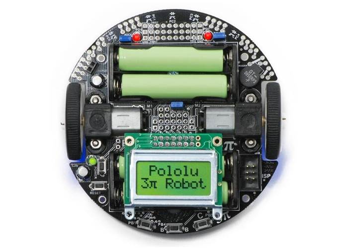
The diagrams below highlight the important features of the 3pi. Click on either picture for an expanded view.
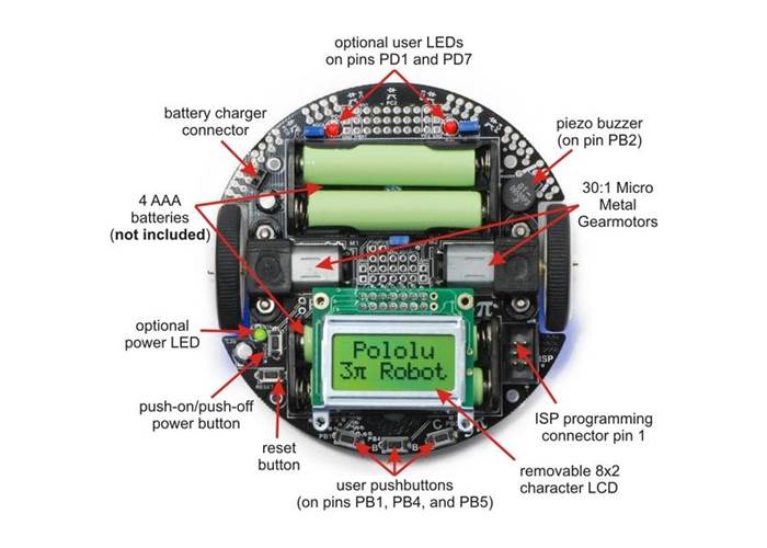

For instructions on setting up and programming the 3pi, including sample code, contest ideas, and more, see the 3pi User’s Guide.
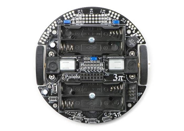
The 3pi is powered by 4 AAA batteries, which are not included. We recommend rechargeable NiMH cells, which may be purchased at many electronics stores. I like these ones from Jaycar but any will do. I'd also recommend getting two sets of batteries because charging takes a while and is very boring.
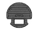
We currently offer two expansion kits for the 3pi that give you room to augment your 3pi with your own custom electronics. One expansion kit features cutouts that let you view the LCD below and allow you to reach the power button, reset button, and ISP programming header on the base.The other expansion kit has no cutouts and instead replaces the LCD, giving you access to more I/O lines and more prototyping space.


To see for yourself what the 3pi is like, please take a look at the video below, which introduces its basic features and operation.
The following video shows a 3pi prototype autonomously solving a line maze. It first runs through the maze executing a search algorithm, keeping track of which way it is turning at intersections and discarding paths that lead to dead ends. Once it finds the end, which is marked by a solid black circle, it determines from memory the best path from start to finish and on subsequent runs aggressively drives that shortest path. This is just one example of what the 3pi is capable of.
This unedited video shows six 3pi prototypes simultaneously participating in a line-following exhibition at a local robotics competition. The robots were all programmed independently. Last one remaining on the line wins!
Click here for even more 3pi videos!
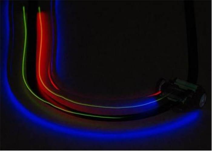
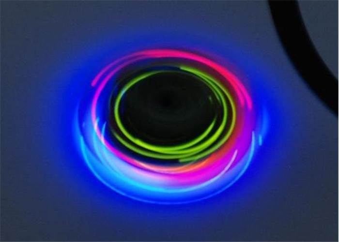
The following pictures show the 3pi’s LEDs as it drives around in the dark:
| Size: | 3.7" diameter |
| Processor: | ATmega168/328P |
| Motor driver: | TB6612FNG |
| Motor channels: | 2 |
| User I/O lines: | 2(1) |
| Minimum operating voltage: | 3 V(2) |
| Maximum operating voltage: | 7 V(2) |
| Maximum PWM frequency: | 80 kHz |
| Reverse voltage protection?: | Y |
| External programmer required?: | Y |
Information about installing and using the C/C++ libraries provided for use with Pololu products.
A reference to commands provided in the Pololu C/C++ and Arduino libraries for the AVR.
Step-by-step instructions for building your own line-following courses.
Guide to making the Arduino IDE compatible with the 3pi robot and the Orangutan SV-168, Orangutan LV-168, and Baby Orangutan B robot controllers, including Arduino libraries for interfacing with the all of their on-board hardware.
Sample robot project for enhancing a 3pi robot to drive around objects on its left.
Sample robot project for making the 3pi radio controlled.
Detailed information about the 3pi Robot, Orangutan SV-328/168 and LV-168, and Baby Orangutan B motor drivers, including truth tables and sample code.
The 3pi robot does not include batteries or a charger. The battery charger connection provides a direct connection to the batteries so that if you use rechargeable batteries, you can recharge them without taking them out of the robot. You will need a charger capable of charging four NiMH or NiCD cells (depending on what you’re using) in series. Such chargers are readily available in hobby stores for charging electric model airplane battery packs. Please note that rechargeable batteries are not required as the 3pi can use regular alkaline cells, but we strongly recommend investing in some NiMH cells and a charger.
I’m ready to order a 3pi, but am wondering what sort of battery charger I need. Any recommendations?
You will only need a battery charger if you plan on powering your 3pi with rechargeable cells. The features you want are ability to charge 4 NiMH cells in series (they are usually in battery packs, not in battery holders like on the 3pi) and to be powered by AC (a wall outlet). In general, having more flexibility (such as the ability to charge 1-8 cells) is nice for future projects.
Since the 3pi just uses ordinary AAA batteries, you can buy battery chargers (into which you stick the batteries) at most general electronics stores. The downside to a charger like this is that you have to remove the batteries from the 3pi to charge them. These chargers are also unsuitable for battery packs where batteries are connected in series such as 7.2v NiMH packs often found in radio controlled cars.
No, this behavior is normal. To get the most out of the ATmega168’s I/O lines, one of the LCD’s data lines (PD7) doubles as the control line for the green LED, so this LED might flicker when the LCD is updated. As such, the amount of flickering and effective brightness of the LED will generally be a function of the rate at which you are updating the LCD. Note that you can change the state of the green LED without affecting the LCD at all, and using the LCD via the Pololu AVR library will only very briefly change the state of the LED line as needed before restoring it to its previous state.
Yes. The easiest way to augment your 3pi is through an expansion kit, which can comes either with cutouts that let you see the LCD below or without cutouts. The version without cutouts replaces the LCD, giving you access to more I/O lines and more prototyping space. An expansion kit is not required for addition of your own electronics, however.
The 3pi robot has a limited number of free I/O lines that can be used as inputs for additional sensors or to control additional electronics such as LEDs or servos. Please see section 10.c of the 3pi user’s guide for more information.
Unfortunately, there is no provision for encoders on the 3pi: we do not have any sensor solution and the microcontroller does not have enough I/O lines. Therefore, the only way to add encoding is to make your own sensor setup and to use an external microcontroller (for example, on an expansion PCB) to do the sensor reading. The secondary microcontroller can communicate with the main 3pi controller using the asynchronous serial lines, which are available for expansion purposes.
Because the 5 V goes through two power stages, the answer is not completely clear-cut. The 5 V regulator itself has a 900 mW power dissipation limit, so with a 4.3 V drop from the 9.3 V boost voltage to 5 V, we get just over 200 mA. The stock electronics on the 3pi typically use under 50 mA (however, this depends on what your program is doing, if you are making high-frequency noise with the buzzer, and so on), so you could figure an absolute max of 150 mA, with 100 mA being a more comfortable guideline.
However, the boost voltage has a limit of its own of around 1 A, which is dependent on your battery voltage. The motors and IR LEDs also use this supply, so using a lot for your 5 V will affect what is available for the motors. You can almost stall the motors and still have the full boost voltage on the motors in the stock configuration; if you’re also drawing an extra 200 mA for other electronics, the boost voltage will start dropping as the motors approach stall, though this is not necessarily a bad thing since it will limit the stress on the motors and lower the voltage drop on the linear regulator.