Ideally suited to a line following robot, the QTR-8RC Relectance Sensor array from Pololu features 8 Infrared (IR) LED/Phototransistor pairs which can be turned off for power savings. Each sensor provides a separate digital I/O measurable output.
In stock in Australia
Shipping from $2.90
+384 more from our supplier in 7-10 days
Our Code: SEN-10017
Supplier Link: [Pololu MPN:961]
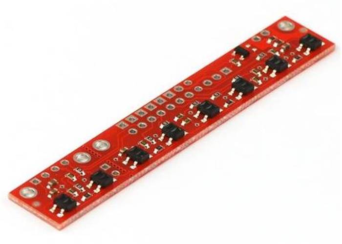
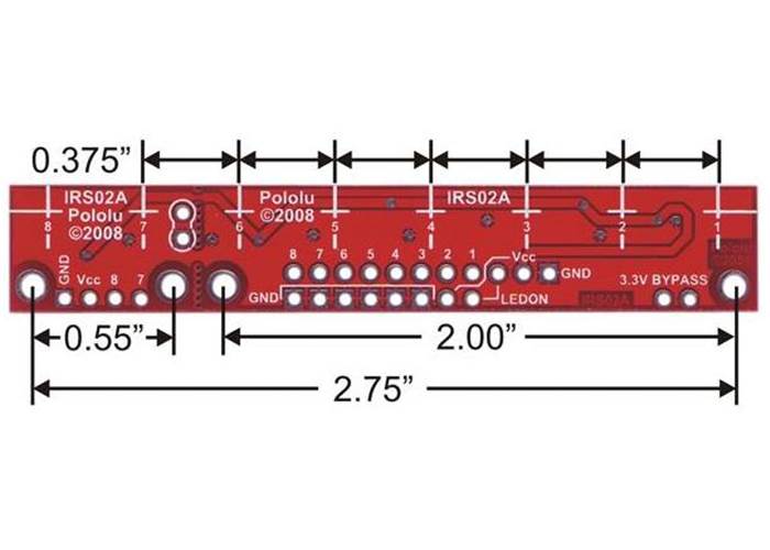
 The QTR-8RC reflectance sensor array is intended as a line sensor, but it can be used as a general-purpose proximity or reflectance sensor. The module is a convenient carrier for eight IR emitter and receiver (phototransistor) pairs evenly spaced at intervals of 0.375" (9.525 mm). Each phototransistor uses a capacitor discharge circuit that allows a digital I/O line on a microcontroller to take an analog reading of reflected IR by measuring the discharge time of the capacitor. Shorter capacitor discharge time is an indication of greater reflection.
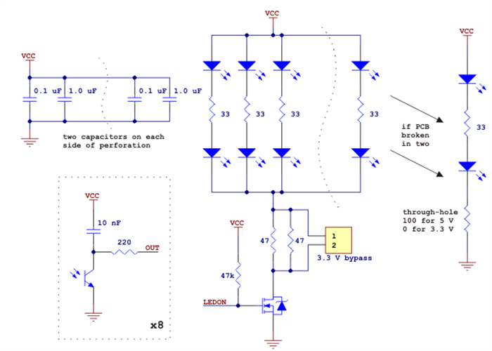
The outputs are all independent, but the LEDs are arranged in pairs to halve current consumption. The LEDs are controlled by a MOSFET with a gate normally pulled high, allowing the LEDs to be turned off by setting the MOSFET gate to a low voltage. Turning the LEDs off might be advantageous for limiting power consumption when the sensors are not in use or for varying the effective brightness of the LEDs through PWM control.
The LED current-limiting resistors for 5 V operation are arranged in two stages; this allows a simple bypass of one stage to enable operation at 3.3 V. The LED current is approximately 20-25 mA, making the total board consumption just under 100 mA. The schematic diagram of the module is shown below:

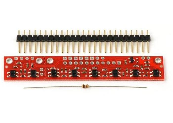
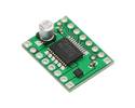
This module ships with a 25-pin 0.1" header strip and a 100 Ohm through-hole resistor as shown below.

You can break the header strip into smaller pieces and solder them onto your reflectance sensor array as desired, or you can solder wires directly to the unit or use a right-angle header strip for a more compact installation. The pins on the module are arranged so that they can all be accessed using either an 11×1 strip or an 8×2 strip.
The resistor is required to make the two-sensor array functional after the original eight-sensor array is broken into two pieces. This resistor is only needed once the board has been broken. See the Operation tab for details.
Like the Parallax QTI, the QTR-8RC module has eight identical sensor outputs that require a digital I/O line capable of first charging the output capacitor (by driving the line high) and then measuring the time for the capacitor to discharge through the phototransistor. This measurement approach has several advantages, especially when coupled with the ability of the QTR-8RC module to turn off LED power:
The typical sequence for reading a sensor is:
These steps can typically be executed in parallel on multiple I/O lines.
With a strong reflectance, the discharge time can be as low as several dozen microseconds; with no reflectance, the discharge time can be up to a few milliseconds. The exact time of the discharge depends on your microcontroller’s I/O line characteristics. Meaningful results can be available within 1 ms in typical cases (i.e. when not trying to measure subtle differences in low-reflectance scenarios), allowing up to 1 kHz sampling of all 8 sensors. If lower-frequency sampling is sufficient, substantial power savings can be realized by turning off the LEDs. For example, if a 100 Hz sampling rate is acceptable, the LEDs can be off 90% of the time, lowering average current consumption from 100 mA to 10 mA.
The Pololu AVR library provides functions that make it easy to use these sensors with the Orangutan robot controllers and other AVR-based controller boards such as Arduinos. Please see section 11 of the Pololu library command reference for more information.
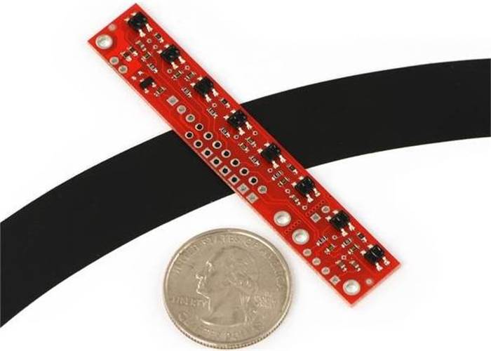
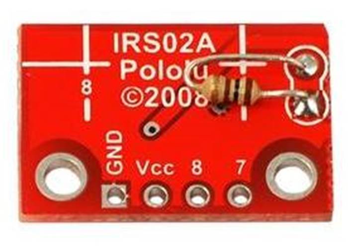
If you don’t need or cannot fit all eight sensors, you can break off two sensors and still use all 8 sensors as two separate modules, as shown below. The PCB can be scored from both sides along the perforation and then bent until it snaps apart. Each of the two resulting pieces will function as an independent line sensor.
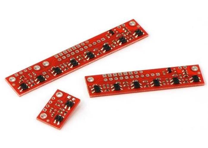
A resistor is required to make the two-sensor array functional after the original eight-sensor array is broken into two pieces. This resistor is only needed once the board has been broken.

1) QTR-8A and QTR-8RC Reflectance Sensor Array User’s Guide (Printable PDF: QTR-8x.pdf)
User's guide for the QTR-8A reflectance sensor array.
2) Pololu QTR Reflectance Sensor Application Note (Printable PDF: QTR_application_note.pdf)
Information about using the Pololu QTR-xA and QTR-xRC reflectance sensors, including sample oscilloscope screen captures of sensor outputs.
Information about installing and using the C/C++ libraries provided for use with Pololu products.
A guide to using the Pololu QTRSensors library with Arduinos and Arduino-compatible devices like the Pololu Orangutan robot controllers.
5) Pololu AVR Library Command Reference (Printable PDF: avr_library_commands.pdf)
A reference to commands provided in the Pololu C/C++ and Arduino libraries for the AVR.
Step-by-step instructions for building your own line-following courses.