This 2.62" × 1.45" × 1.45" gearmotor is a powerful 12V motor with a 50:1 metal gearbox and an integrated quadrature encoder that provides a resolution of 64 counts per revolution of the motor shaft, which corresponds to 3200 counts per revolution of the gearbox’s output shaft. These units have a 0.61"-long, 6 mm-diameter D-shaped output shaft.
Not currently available
Our Code: MEC-30071
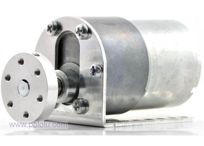 The face plate has six mounting holes evenly spaced around the outer edge threaded for M3 screws. These mounting holes form a regular hexagon and the centers of neighboring holes are 15.5 mm apart. You can use our custom 37D mm metal gearmotor bracket (shown in the right picture) to mount the gearmotor to your project via these mounting holes and the screws that come with the bracket.
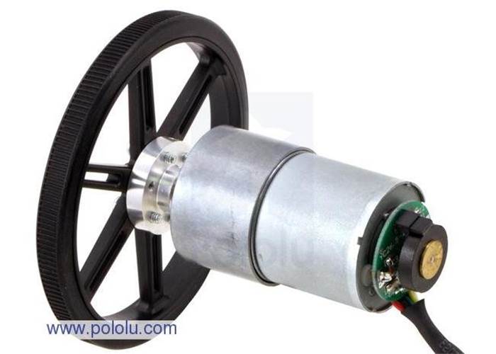
Please note that unlike our smaller metal gearmotors, these 37D mm gearmotors have output shafts with a diameter of 6 mm. The Pololu universal aluminum mounting hub for 6mm shafts can be used to mount our larger Pololu wheels (80mm- and 90mm-diameter) or custom wheels and mechanisms to the gearmotor’s output shaft (see the picture below).

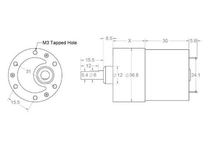
The diagram below shows the dimensions (in mm) of the 37D mm line of gearmotors. The value of X is 22 mm for the 19:1 37Dx52L mm and 29:1 37Dx52L mm versions, 24 mm for the 50:1 37Dx54L mm and 67:1 37Dx54L mm versions, and 26.5 mm for the 100:1 37Dx57L mm and 122:1 37Dx57L mm versions. Note that the encoder PCB and magnetic disc are not shown in this dimension diagram. The encoder assembly extends an additional 12.5 mm beyond the rear of the motor.
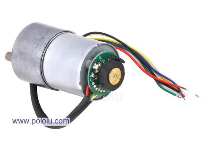
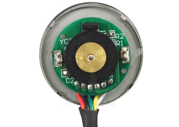 A two-channel Hall effect encoder is used to sense the rotation of a magnetic disk on a rear protrusion of the motor shaft. The quadrature encoder provides a resolution of 64 counts per revolution of the motor shaft. To compute the counts per revolution of the gearbox output, multiply the gear ratio by 64. The motor/encoder has six color-coded, 11" (28 cm) leads:
| Color | Function |
|---|---|
| Black | motor power |
| Red | motor power |
| Blue | Hall sensor Vcc (3.5 – 20 V) |
| Green | Hall sensor GND |
| Yellow | Hall sensor A output |
| White | Hall sensor B output |
These leads have stripped, unterminated ends that can be soldered or crimped to make solder free connectors. The Hall sensor requires an input voltage, Vcc, between 3.5 and 20 V and draws a maximum of 10 mA. The A and B outputs are square waves from 0 V to Vcc approximately 90° out of phase. The frequency of the transitions tells you the speed of the motor, and the order of the transitions tells you the direction.
By counting both the rising and falling edges of both the A and B outputs, it is possible to get 64 counts per revolution of the motor shaft. Using just a single edge of one channel results in 16 counts per revolution of the motor shaft, so the frequency of the A output in the above oscilloscope capture is 16 times the motor rotation frequency.
| Size: | 37D x 66L mm |
| Weight: | 7.7 oz |
| Shaft diameter: | 6 mm |
| Gear ratio: | 50:1 |
| Free-run speed @ 12V: | 200 rpm |
| Free-run current @ 12V: | 300 mA |
| Stall current @ 12V: | 5000 mA |
| Stall torque @ 12V: | 170 oz·in |
| Free-run speed @ 6V: | 100 rpm |
| Free-run current @ 6V: | 250 mA |
| Stall current @ 6V: | 2500 mA |
| Stall torque @ 6V: | 85 oz·in |
| Lead length: | 11 in |