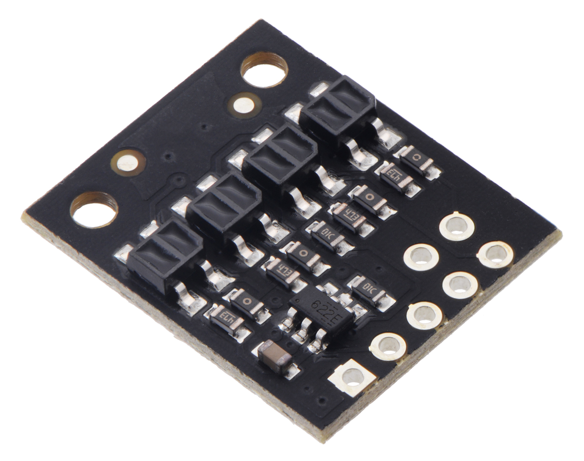
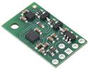
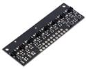
sensors size (mm) output max current optimal range LED board 1 5.0 × 20.0 analogue 30 mA 32 mA 20 mm This IR LED/phototransistor pair is great for precisely identifying changes in reflectance (like line detection).
Special Order
Shipping from $4.90
+360 more from our supplier in 7-10 days
Our Code: SKU-004919
Supplier Link: [Pololu MPN:4601]
| sensors | size (mm) |
output | max current | optimal range |
|
|---|---|---|---|---|---|
| LED | board | ||||
| 1 | 5.0 × 20.0 | analog | 30 mA | 32 mA | 20 mm |
This IR LED/phototransistor pair is great for precisely identifying changes in reflectance (like line detection). It operates from 2.9 V to 5.5 V and offers dimmable brightness control independent of the supply voltage. In general, the closer the object, the higher the contrast between light and dark readings, but high-reflectance objects are generally detectable out to around 80 mm. This version features a high-performance QTRXL sensor with lenses and a high-brightness emitter for extra-long range.
Pinout diagram of the QTRX/QTRXL-HD-01A Reflectance Sensor Array. |
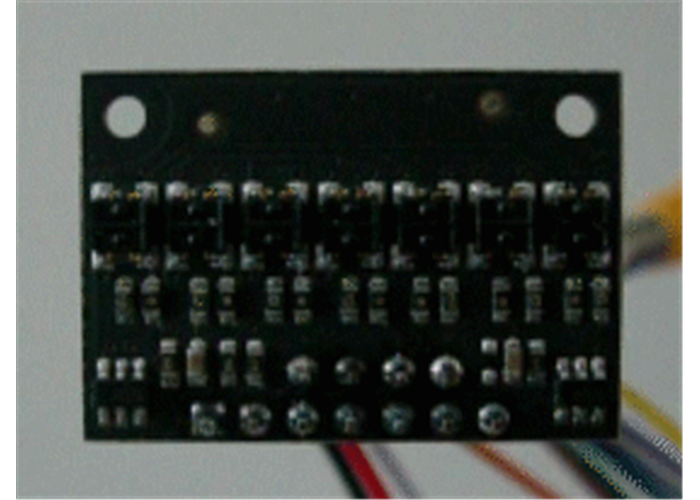
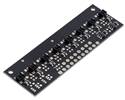
QTRXL-HD-01A Reflectance Sensor, front and back views. |

QTRX/QTRXL-HD-01A Reflectance Sensor dimensions.
| QTR sensors 2.9 V to 5.5 V; 30 mA max LED current(1); 5 mm optimal range |
|||||||||||||||||||||||||||||||||||||
| Board width |
Configuration | Max board current(2) |
Max range | Output type |
Name | 1-piece price |
|||||||||||||||||||||||||||||||
|---|---|---|---|---|---|---|---|---|---|---|---|---|---|---|---|---|---|---|---|---|---|---|---|---|---|---|---|---|---|---|---|---|---|---|---|---|---|
| 5.0 mm | 1 sensor (HD) |
32 mA | 30 mm | analogue | QTR-HD-01A | $3.25 | |||||||||||||||||||||||||||||||
| RC (digital) | QTR-HD-01RC | $3.25 | |||||||||||||||||||||||||||||||||||
| 7.5 mm | 1 sensor (MD) |
32 mA | 30 mm | analogue | QTR-MD-01A | $2.75 | |||||||||||||||||||||||||||||||
| RC (digital) | QTR-MD-01RC | $2.75 | |||||||||||||||||||||||||||||||||||
| 8.1 mm | 1 sensor with connector (MD-S) |
32 mA | 30 mm | analogue | QTR-MD-01A-S | $3.95 | |||||||||||||||||||||||||||||||
| RC (digital) | QTR-MD-01RC-S | $3.95 | |||||||||||||||||||||||||||||||||||
| 10.2 mm | 4 mm × 2 |
32 mA | 30 mm | analogue | QTR-HD-02A | $3.33 | |||||||||||||||||||||||||||||||
| RC (digital) | QTR-HD-02RC | $3.33 | |||||||||||||||||||||||||||||||||||
| 13.0 mm | 8 mm × 2 |
32 mA | 30 mm | analogue | QTR-MD-02A | $3.44 | |||||||||||||||||||||||||||||||
| RC (digital) | QTR-MD-02RC | $3.44 | |||||||||||||||||||||||||||||||||||
| 4 mm × 3 |
62 mA | 30 mm | analogue | QTR-HD-03A | $4.15 | ||||||||||||||||||||||||||||||||
| RC (digital) | QTR-HD-03RC | $4.15 | |||||||||||||||||||||||||||||||||||
| 17.0 mm | 4 mm × 4 |
62 mA | 40 mm | analogue | QTR-HD-04A | $4.97 | |||||||||||||||||||||||||||||||
| RC (digital) | QTR-HD-04RC | $4.97 | |||||||||||||||||||||||||||||||||||
| 21.0 mm | 8 mm × 3 |
62 mA | 30 mm | analogue | QTR-MD-03A | $4.25 | |||||||||||||||||||||||||||||||
| RC (digital) | QTR-MD-03RC | $4.25 | |||||||||||||||||||||||||||||||||||
| 4 mm × 5 |
93 mA | 40 mm | analogue | QTR-HD-05A | $6.75 | ||||||||||||||||||||||||||||||||
| RC (digital) | QTR-HD-05RC | $6.75 | |||||||||||||||||||||||||||||||||||
| 25.0 mm | 4 mm × 6 |
93 mA | 40 mm | analogue | QTR-HD-06A | $7.60 | |||||||||||||||||||||||||||||||
| RC (digital) | QTR-HD-06RC | $7.60 | |||||||||||||||||||||||||||||||||||
| 29.0 mm | 8 mm × 4 |
62 mA | 40 mm | analogue | QTR-MD-04A | $5.26 | |||||||||||||||||||||||||||||||
| RC (digital) | QTR-MD-04RC | $5.26 | |||||||||||||||||||||||||||||||||||
| 4 mm × 7 |
125 mA | 40 mm | analogue | QTR-HD-07A | $8.31 | ||||||||||||||||||||||||||||||||
| RC (digital) | QTR-HD-07RC | $8.31 | |||||||||||||||||||||||||||||||||||
| 37.0 mm | 8 mm × 5 |
93 mA | 40 mm | analogue | QTR-MD-05A | $7.02 | |||||||||||||||||||||||||||||||
| RC (digital) | QTR-MD-05RC | $7.02 | |||||||||||||||||||||||||||||||||||
| 4 mm × 9 |
155 mA | 40 mm | analogue | QTR-HD-09A | $11.12 | ||||||||||||||||||||||||||||||||
| RC (digital) | QTR-HD-09RC | $11.12 | |||||||||||||||||||||||||||||||||||
| 45.0 mm | 8 mm × 6 |
93 mA | 40 mm | analogue | QTR-MD-06A | $8.01 | |||||||||||||||||||||||||||||||
| RC (digital) | QTR-MD-06RC | $8.01 | |||||||||||||||||||||||||||||||||||
| 4 mm × 11 |
185 mA | 40 mm | analogue | QTR-HD-11A | $13.73 | ||||||||||||||||||||||||||||||||
| RC (digital) | QTR-HD-11RC | $13.73 | |||||||||||||||||||||||||||||||||||
| 53.0 mm | 8 mm × 7 |
125 mA | 40 mm | analogue | QTR-MD-07A | $8.90 | |||||||||||||||||||||||||||||||
| RC (digital) | QTR-MD-07RC | $8.90 | |||||||||||||||||||||||||||||||||||
| 4 mm × 13 |
220 mA | 40 mm | analogue | QTR-HD-13A | $15.21 | ||||||||||||||||||||||||||||||||
| RC (digital) | QTR-HD-13RC | $15.21 | |||||||||||||||||||||||||||||||||||
| 61.0 mm | 8 mm × 8 |
125 mA | 40 mm | analogue | QTR-MD-08A | $9.90 | |||||||||||||||||||||||||||||||
| RC (digital) | QTR-MD-08RC | $9.90 | |||||||||||||||||||||||||||||||||||
| 4 mm × 15 |
250 mA | 50 mm | analogue | QTR-HD-15A | $16.88 | ||||||||||||||||||||||||||||||||
| RC (digital) | QTR-HD-15RC | $16.88 | |||||||||||||||||||||||||||||||||||
| 101.0 mm | 8 mm × 13 |
220 mA | 40 mm | analogue | QTR-MD-13A | $16.43 | |||||||||||||||||||||||||||||||
| RC (digital) | QTR-MD-13RC | $16.43 | |||||||||||||||||||||||||||||||||||
| 4 mm × 25 |
405 mA | 50 mm | analogue | QTR-HD-25A | $30.09 | ||||||||||||||||||||||||||||||||
| RC (digital) | QTR-HD-25RC | $30.09 | |||||||||||||||||||||||||||||||||||
| 125.0 mm | 8 mm × 16 |
250 mA | 50 mm | analogue | QTR-MD-16A | $19.21 | |||||||||||||||||||||||||||||||
| RC (digital) | QTR-MD-16RC | $19.21 | |||||||||||||||||||||||||||||||||||
| 4 mm × 31 |
495 mA | 50 mm | analogue | QTR-HD-31A | $35.11 | ||||||||||||||||||||||||||||||||
| RC (digital) | QTR-HD-31RC | $35.11 | |||||||||||||||||||||||||||||||||||
| QTRX sensors 2.9 V to 5.5 V; 3.5 mA max LED current(1); 10 mm optimal range |
|||||||||||||||||||||||||||||||||||||
| Board width |
Configuration | Max board current(2) |
Max range | Output type |
Name | 1-piece price |
|||||||||||||||||||||||||||||||
| 5.0 mm | 1 sensor (HD) |
5 mA | 30 mm | analogue | QTRX-HD-01A | $3.75 | |||||||||||||||||||||||||||||||
| RC (digital) | QTRX-HD-01RC | $3.75 | |||||||||||||||||||||||||||||||||||
| 7.5 mm | 1 sensor (MD) |
5 mA | 30 mm | analogue | QTRX-MD-01A | $3.25 | |||||||||||||||||||||||||||||||
| RC (digital) | QTRX-MD-01RC | $3.25 | |||||||||||||||||||||||||||||||||||
| 8.1 mm | 1 sensor with connector (MD-S) |
5 mA | 30 mm | analogue | QTRX-MD-01A-S | $4.29 | |||||||||||||||||||||||||||||||
| RC (digital) | QTRX-MD-01RC-S | $4.29 | |||||||||||||||||||||||||||||||||||
| 10.2 mm | 4 mm × 2 |
5 mA | 30 mm | analogue | QTRX-HD-02A | $4.99 | |||||||||||||||||||||||||||||||
| RC (digital) | QTRX-HD-02RC | $4.99 | |||||||||||||||||||||||||||||||||||
| 13.0 mm | 8 mm × 2 |
5 mA | 30 mm | analogue | QTRX-MD-02A | $4.99 | |||||||||||||||||||||||||||||||
| RC (digital) | QTRX-MD-02RC | $4.99 | |||||||||||||||||||||||||||||||||||
| 4 mm × 3 |
9 mA | 30 mm | analogue | QTRX-HD-03A | $6.51 | ||||||||||||||||||||||||||||||||
| RC (digital) | QTRX-HD-03RC | $6.51 | |||||||||||||||||||||||||||||||||||
| 17.0 mm | 4 mm × 4 |
9 mA | 40 mm | analogue | QTRX-HD-04A | $8.25 | |||||||||||||||||||||||||||||||
| RC (digital) | QTRX-HD-04RC | $8.25 | |||||||||||||||||||||||||||||||||||
| 21.0 mm | 8 mm × 3 |
9 mA | 30 mm | analogue | QTRX-MD-03A | $6.74 | |||||||||||||||||||||||||||||||
| RC (digital) | QTRX-MD-03RC | $6.74 | |||||||||||||||||||||||||||||||||||
| 4 mm × 5 |
14 mA | 40 mm | analogue | QTRX-HD-05A | $10.76 | ||||||||||||||||||||||||||||||||
| RC (digital) | QTRX-HD-05RC | $10.76 | |||||||||||||||||||||||||||||||||||
| 25.0 mm | 4 mm × 6 |
14 mA | 40 mm | analogue | QTRX-HD-06A | $12.47 | |||||||||||||||||||||||||||||||
| RC (digital) | QTRX-HD-06RC | $12.47 | |||||||||||||||||||||||||||||||||||
| 29.0 mm | 8 mm × 4 |
9 mA | 40 mm | analogue | QTRX-MD-04A | $8.41 | |||||||||||||||||||||||||||||||
| RC (digital) | QTRX-MD-04RC | $8.41 | |||||||||||||||||||||||||||||||||||
| 4 mm × 7 |
17 mA | 40 mm | analogue | QTRX-HD-07A | $14.05 | ||||||||||||||||||||||||||||||||
| RC (digital) | QTRX-HD-07RC | $14.05 | |||||||||||||||||||||||||||||||||||
| 37.0 mm | 8 mm × 5 |
14 mA | 40 mm | analogue | QTRX-MD-05A | $11.08 | |||||||||||||||||||||||||||||||
| RC (digital) | QTRX-MD-05RC | $11.08 | |||||||||||||||||||||||||||||||||||
| 4 mm × 9 |
22 mA | 40 mm | analogue | QTRX-HD-09A | $18.17 | ||||||||||||||||||||||||||||||||
| RC (digital) | QTRX-HD-09RC | $18.17 | |||||||||||||||||||||||||||||||||||
| 45.0 mm | 8 mm × 6 |
14 mA | 40 mm | analogue | QTRX-MD-06A | $12.80 | |||||||||||||||||||||||||||||||
| RC (digital) | QTRX-MD-06RC | $12.80 | |||||||||||||||||||||||||||||||||||
| 4 mm × 11 |
26 mA | 40 mm | analogue | QTRX-HD-11A | $22.40 | ||||||||||||||||||||||||||||||||
| RC (digital) | QTRX-HD-11RC | $22.40 | |||||||||||||||||||||||||||||||||||
| 53.0 mm | 8 mm × 7 |
17 mA | 40 mm | analogue | QTRX-MD-07A | $14.44 | |||||||||||||||||||||||||||||||
| RC (digital) | QTRX-MD-07RC | $14.44 | |||||||||||||||||||||||||||||||||||
| 4 mm × 13 |
31 mA | 40 mm | analogue | QTRX-HD-13A | $26.03 | ||||||||||||||||||||||||||||||||
| RC (digital) | QTRX-HD-13RC | $26.03 | |||||||||||||||||||||||||||||||||||
| 61.0 mm | 8 mm × 8 |
17 mA | 40 mm | analogue | QTRX-MD-08A | $16.22 | |||||||||||||||||||||||||||||||
| RC (digital) | QTRX-MD-08RC | $16.22 | |||||||||||||||||||||||||||||||||||
| 4 mm × 15 |
34 mA | 50 mm | analogue | QTRX-HD-15A | $29.10 | ||||||||||||||||||||||||||||||||
| RC (digital) | QTRX-HD-15RC | $29.10 | |||||||||||||||||||||||||||||||||||
| 101.0 mm | 8 mm × 13 |
31 mA | 40 mm | analogue | QTRX-MD-13A | $26.87 | |||||||||||||||||||||||||||||||
| RC (digital) | QTRX-MD-13RC | $26.87 | |||||||||||||||||||||||||||||||||||
| 4 mm × 25 |
56 mA | 50 mm | analogue | QTRX-HD-25A | $50.62 | ||||||||||||||||||||||||||||||||
| RC (digital) | QTRX-HD-25RC | $50.62 | |||||||||||||||||||||||||||||||||||
| 125.0 mm | 8 mm × 16 |
34 mA | 50 mm | analogue | QTRX-MD-16A | $31.95 | |||||||||||||||||||||||||||||||
| RC (digital) | QTRX-MD-16RC | $31.95 | |||||||||||||||||||||||||||||||||||
| 4 mm × 31 |
68 mA | 50 mm | analogue | QTRX-HD-31A | $60.01 | ||||||||||||||||||||||||||||||||
| RC (digital) | QTRX-HD-31RC | $60.01 | |||||||||||||||||||||||||||||||||||
| QTRXL sensors 2.9 V to 5.5 V; 30 mA max LED current(1); 20 mm optimal range |
|||||||||||||||||||||||||||||||||||||
| Board width |
Configuration | Max board current(2) |
Max range | Output type |
Name | 1-piece price |
|||||||||||||||||||||||||||||||
| 5.0 mm | 1 sensor (HD) |
32 mA | 80 mm | analogue | QTRXL-HD-01A | $3.75 | |||||||||||||||||||||||||||||||
| RC (digital) | QTRXL-HD-01RC | $3.75 | |||||||||||||||||||||||||||||||||||
| 7.5 mm | 1 sensor (MD) |
32 mA | 80 mm | analogue | QTRXL-MD-01A | $3.37 | |||||||||||||||||||||||||||||||
| RC (digital) | QTRXL-MD-01RC | $3.37 | |||||||||||||||||||||||||||||||||||
| 8.1 mm | 1 sensor with connector (MD-S) |
32 mA | 80 mm | analogue | QTRXL-MD-01A-S | $4.29 | |||||||||||||||||||||||||||||||
| RC (digital) | QTRXL-MD-01RC-S | $4.29 | |||||||||||||||||||||||||||||||||||
| 1 Can be dynamically reduced to any of 32 available dimming levels. 2 With all LEDs on at max brightness setting. |
|||||||||||||||||||||||||||||||||||||
These reflectance sensors feature a linear array of infrared emitter/phototransistor pair modules in a high-density (4 mm pitch) or medium-density (8 mm pitch) arrangement, which makes them well suited for applications that require detection of changes in reflectivity. This change in reflectivity can be due to a colour change at a fixed distance, such as when sensing a black line on a white background, as well as due to a change in the distance to or presence of an object in front of the sensor. A variety of sensor counts and densities is available so you can pick the ideal arrangement for your application. Since the outputs are all independent, you can connect just some of the channels to attain an irregular or non-standard sensor spacing.

The QTR Reflectance Sensor Arrays are available in many different sizes.
Unlike our original QTR sensor modules, these units have integrated LED drivers that provide brightness control independent of the supply voltage, which can be anywhere from 2.9 V to 5.5 V, while enabling optional dimming to any of 32 possible brightness settings. For high-density (HD) modules with five or more sensors and medium-density (MD) modules with eleven or more sensors, there are separate controls for the odd-numbered and even-numbered LEDs, which gives you extra options for detecting light reflected at various angles. See the “Emitter control” section below for more information on using this feature.
Two different sensor options are available, denoted by “QTR” or “QTRX” in the product name. The “QTR” versions feature lower-cost sensor modules without lenses while the “QTRX” versions feature higher-performance sensor modules with lenses, which allow similar performance at a much lower IR LED current. You can see the two different sensor styles in the pictures below of the 4-channel modules:
|
|
We also have several single-channel modules with the “QTRXL” designator that offer extra-long range by using the QTRX-style sensor module with higher current through the emitter.
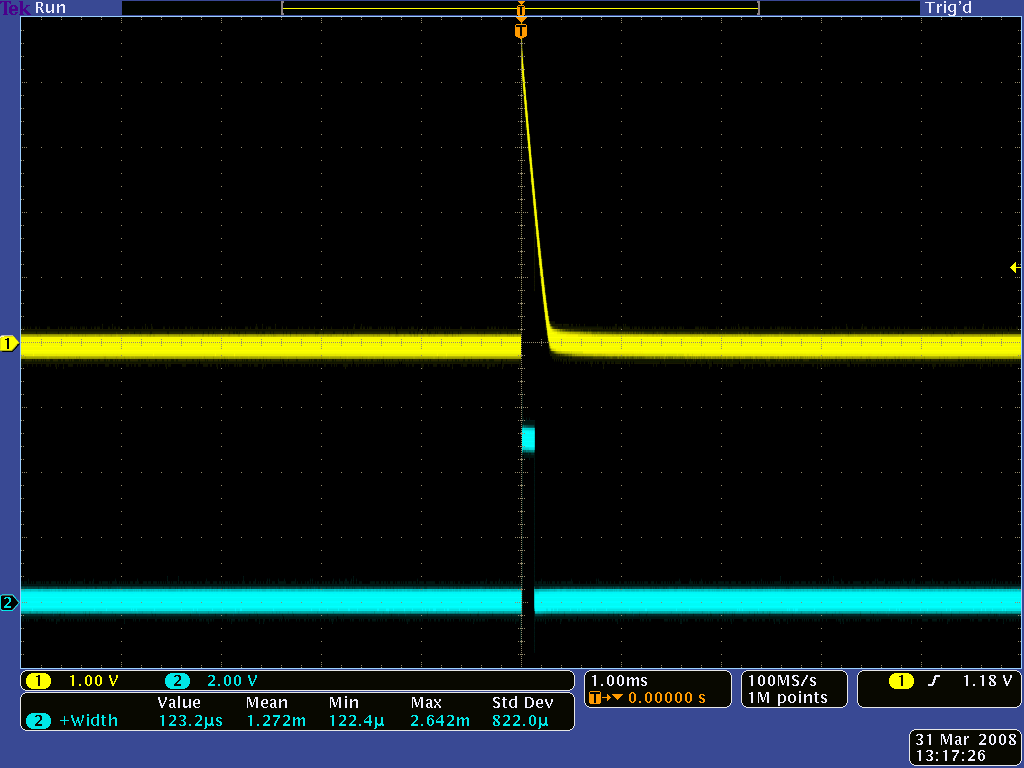
Each sensor option is available in two output types: an “A” version with analogue voltage outputs between 0 V and VCC, and an “RC” version with outputs that can be read with a digital I/O line on a microcontroller by first setting the lines high and then releasing them and timing how long it takes them to read as low (typically anywhere from a few microseconds to a few milliseconds). The lower the output voltage or shorter the voltage decay time, the higher the reflectance. The following simplified schematic diagrams show the circuits for the individual channels:
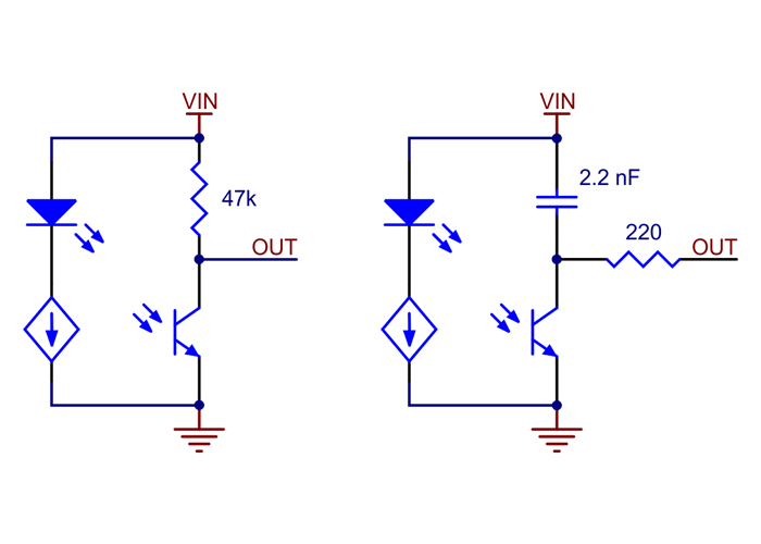
Schematic diagrams of individual QTR sensor channels for A version (left) and RC version (right). This applies only to the newer QTRs with dimmable emitters.
Our Arduino library makes it easy to use these sensor modules with an Arduino or compatible controller by providing methods for controlling the emitters, calibrating the module, and reading the individual sensor values from either the A or RC versions. It also has a method specifically for line-following applications to compute the location of the line under the array.
Note: With the exception of the 1-channel QTR/QTRX/QTRXL-MD-01x-S versions with side-entry connectors, these QTR modules do not ship with any headers or connectors included, so you will need to supply your own or solder wires directly to the board to use them. See our selection of male headers, female headers, and pre-crimped wires for various connector options.
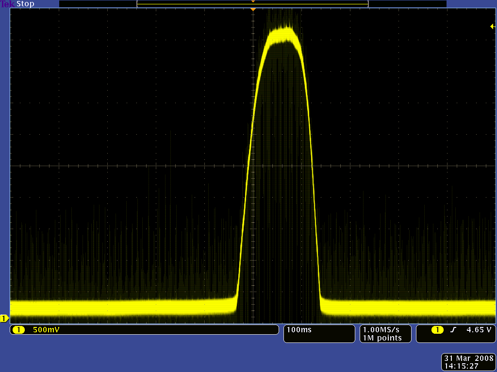
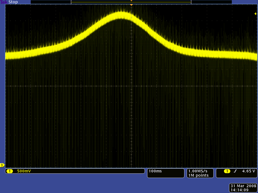
Each sensor on the A versions outputs its reflectance measurement as an analogue voltage that can range from 0 V when the reflectance is very strong to VCC when the reflectance is very weak. There are several ways you can interface with the analogue output:
This last method will work if you are able to get high reflectance from your white surface as depicted in the left image, but will probably fail if you have a lower-reflectance signal profile like the one on the right.
|
|
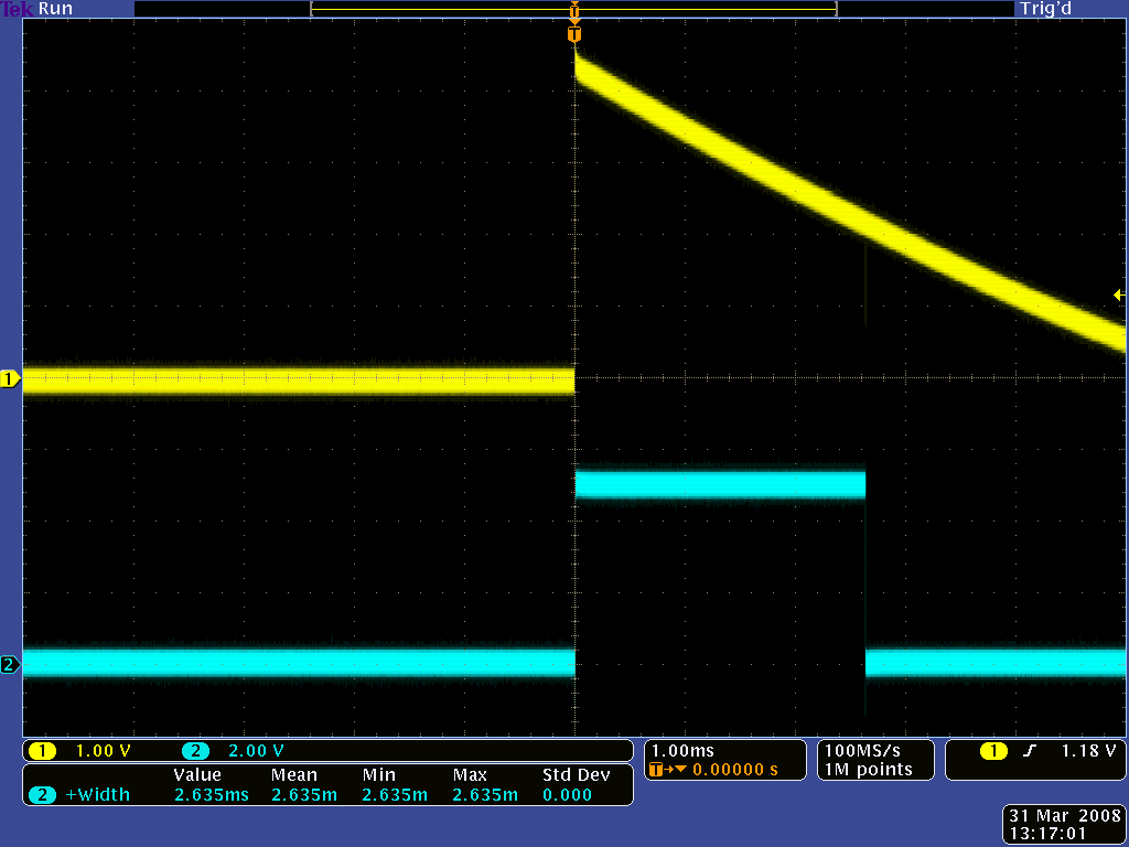
Each sensor on the RC versions requires a digital I/O line capable of driving the output line high and then measuring the time for the output voltage to decay. The typical sequence for reading a sensor is:
|
|
These steps can typically be executed in parallel on multiple I/O lines.
With a strong reflectance, the decay time can be as low as a few microseconds; with no reflectance, the decay time can be up to a few milliseconds. The exact time of the decay depends on your microcontroller’s I/O line characteristics. Meaningful results can be available within 1 ms in typical cases (i.e. when not trying to measure subtle differences in low-reflectance scenarios), allowing up to 1 kHz sampling of all sensors. If lower-frequency sampling is sufficient, you can achieve substantial power savings by turning off the LEDs. For example, if a 100 Hz sampling rate is acceptable, the LEDs can be off 90% of the time, lowering average current consumption from 125 mA to 13 mA.
These reflectance sensor arrays maintain a constant current through their IR emitters, keeping the emitters’ brightness constant, independent of the supply voltage (2.9 V to 5.5 V). The emitters can be controlled with the board’s CTRL pins, and the details of the control depends on the array size and density:
Driving a CTRL pin low for at least 1 ms turns off the associated emitter LEDs, while driving it high (or allowing the board to pull it high) turns on the emitters with the board’s default (full) LED current, which is 30 mA for “QTR” versions and 3.5 mA for “QTRX” versions. (The emitter LEDs are generally driven in pairs, with the two emitters in each pair connected in series, so the total board current is not the LED current times the number of LEDs as you might otherwise expect; it is usually closer to half that.)
|
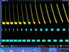
Demo of IR LED dimming and independent even/odd control on the QTRX-HD-07x (as seen through an old digital camera that can see IR). |
For more advanced use, the CTRL pin can be pulsed low to cycle the associated emitters through 32 dimming levels. To send a pulse, drive the CTRL pin low for at least 0.5 μs (but no more than 300 μs), then high for at least 0.5 μs; (it should remain high after the last pulse). Each pulse causes the driver to advance to the next dimming level, wrapping around to 100% after the lowest-current level. Each dimming level corresponds to a 3.33% reduction in current, except for the last three levels, which represent a 1.67% reduction, as shown in the table below. Note that turning the LEDs off with a >1 ms pulse and then back on resets them to full current.
| Dimming level (pulses) |
Emitter current (%) |
Dimming level (pulses) |
Emitter current (%) |
|
|---|---|---|---|---|
| 0 | 100.00% | 16 | 46.67% | |
| 1 | 96.67% | 17 | 43.33% | |
| 2 | 93.33% | 18 | 40.00% | |
| 3 | 90.00% | 19 | 36.67% | |
| 4 | 86.67% | 20 | 33.33% | |
| 5 | 83.33% | 21 | 30.00% | |
| 6 | 80.00% | 22 | 26.67% | |
| 7 | 76.67% | 23 | 23.33% | |
| 8 | 73.33% | 24 | 20.00% | |
| 9 | 70.00% | 25 | 16.67% | |
| 10 | 66.67% | 26 | 13.33% | |
| 11 | 63.33% | 27 | 10.00% | |
| 12 | 60.00% | 28 | 6.67% | |
| 13 | 56.67% | 29 | 5.00% | |
| 14 | 53.33% | 30 | 3.33% | |
| 15 | 50.00% | 31 | 1.67% |
For example, to reduce the emitter current to 50%, apply 15 low pulses to the CTRL pin and then keep it high after the last pulse.
| Size: | 5.0 × 20.0 × 4.4 mm |
|---|---|
| Weight: | 0.25 g |
| Maximum range: | 80 mm |
|---|---|
| Optimal range: | 20 mm |
| Minimum operating voltage: | 2.9 V |
| Maximum operating voltage: | 5.5 V |
| LED current: | 30 mA1 |
| Peak wavelength: | 940 nm |
| Maximum current draw: | 32 mA2 |
| Sensor type: | QTRXL |
| Sensor count: | 1 |
| Output type: | A (analogue voltages) |
| PCB dev codes: | irs21j3 |
|---|---|
| Other PCB markings: | 0J113773 |
Information about using the Pololu QTR reflectance sensors, including differences between A-type and RC-type sensors and sample oscilloscope screen captures of sensor outputs.
This file contains 3D models (in the step file format) of the QTR and QTRX Reflectance Sensor Arrays.
These DXF drawings show the locations of all of the holes on the QTR and QTRX Reflectance Sensor Arrays.
This library for Arduino makes it easy to interface with Pololu QTR Reflectance Sensors.