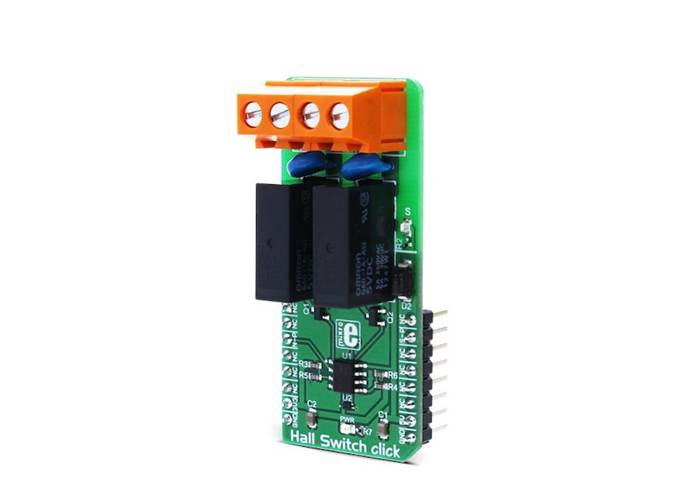
Hall Switch Click is a magnetic field activated dual-relay Click board™. Hall Switch Click has two high-quality relays, which are activated by the Hall-effect sensor: when the north pole magnetic field is introduced to the sensor, one of the relays will be activated; when the south pole magnetic ...
Hall Switch Click is a magnetic field activated dual-relay Click board™. Hall Switch Click has two high-quality relays, which are activated by the Hall-effect sensor: when the north pole magnetic field is introduced to the sensor, one of the relays will be activated; when the south pole magnetic field is introduced to the sensor, the other relay will be activated. Two high-quality compact relays allow switching of high voltages - up to 220V, so they can cut or establish a connection on the main side of the circuit.
This allows for the implementation of various applications activated by the magnetic field, such as the contactless switches, door, lids or tray position detecting switches, or other similar applications that require contactless switching of the relay contacts.
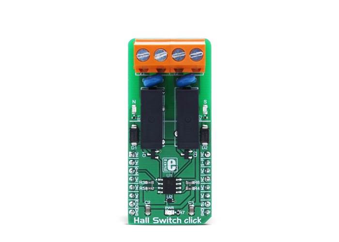
The main active element of the Hall Switch Click is the AH1389, an ultra-sensitive dual output unipolar Hall Effect switch, from Diodes Incorporated. This IC utilizes Hall effect - a phenomenon in which the current flow, or rather - the path of the conductor electrons is affected by the magnetic field. Due to the fact that the path of the electrons is curved, a buildup of positive charges is formed on the opposite side of this path, and the voltage is generated. If a voltmeter is connected to the path perpendicular to the current path and the magnetic field, a voltage will be detected.
The AH1389 has the ability to detect both the north and south poles of the magnetic field. The magnetic field from the south pole magnet will pull the output 2 to a LOW (active) state, while the magnetic field from the north pole magnet will pull the output 1 to a LOW (active) state. The IC features several sections for the signal conditioning. It also provides the hysteresis for the output activation, to avoid erratic triggering. The magnetic field strength which activates outputs is about ±25 G, while the field strength under ±20 G will deactivate outputs, giving a hysteresis of typical 5 G. The positive and negative sign is used with respect to the magnet poles (north pole has a negative sign prefix).
The outputs of the AH1389 IC are routed to the operational amplifiers, which work as the inverting comparators. When the output of the AH1389 IC is activated - pulled to a LOW voltage level, the output from the comparator will be set to 5V. This will cause biasing of the BJT, allowing current flow through the relay coil, and thus forming a magnetic field necessary for closing the relay contacts. A Schottky diode across the relay coil prevents the reverse kickback voltage, which forms due to the inert nature of the coils. Activation of the relay coils is indicated by the red and blue LEDs, respectively.
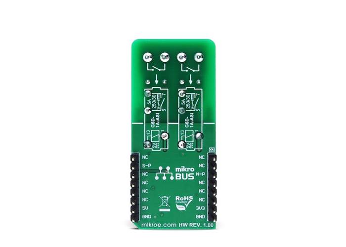
Two outputs of the AH1389 IC are also routed to the mikroBUS pins: north pole output (1) is routed to the CS pin and the south pole output (2) is routed to the INT pin of the mikroBUS™ so that the status of the IC can be monitored by the MCU.
Two varistors are used to prevent voltage peaks when the load is connected or disconnected on the relay output contacts. The output contacts are further routed to the screw terminals, which allow up to 10A. However the relays allow up to 5A for 250V AC/30V DC, so the connected load should not exceed these power ratings.
Note: Hall Switch Click has exposed pins/pads. To stay safe, please take precaution when applying a high voltage to the Click. The Click is to be used by trained personnel only when operating with hazardous voltage levels.