The Pololu basic relay carrier modules allow simple control of a single-pole, double-throw (SPDT) switch from low-voltage, low-current control signals.
Special Order
Shipping from $7.90
+29 more from our supplier in 7-10 days
Our Code: SKU-003254
Supplier Link: [Pololu MPN:2483]

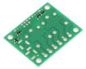
Pololu basic SPDT relay carrier with dimensions

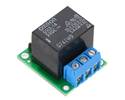
Pololu basic SPDT relay carrier with relay energized
The Pololu basic relay carrier modules make it easy to control a single-pole, double-throw (SPDT) switch from low-voltage, low-current control signals. The modules are available with 5 V and 12 V power relays—Omron G5LE-14-DC5 and G5LE-14-DC12 (1MB pdf), respectively—and they are available pre-soldered or as partial kits that allow greater application flexibility:
Select options:The carrier board is available without the relay or connectors for those preferring to use their own relays that have the common “sugar cube” pinout and footprint, and we also offer several dual-relay carrier modules.
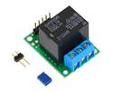
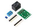
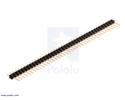
The carrier board routes the three relay control pins to 0.1″-spaced pins compatible with standard solderless breadboads and female servo cable connectors. The assembled version of this board has a 0.1″ straight male header soldered to these pins while the partial kit version includes 8×1 straight and right angle 0.1″ male header strips that can optionally be broken into 3×1 pieces and soldered in. The relay switch pins are routed to a set of large pads intended for use with a 3-pin 5mm-pitch terminal block and a set of smaller pads with a 0.2″ pitch, making them compatible with 0.1″ perfboards. The assembled version of this board has a terminal block soldered to these pins while the partial kit version includes a 3-pin terminal block that can be optionally soldered in. The carrier board has four mounting holes that work with #2 or M2 screws.
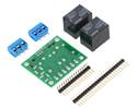
Pololu basic SPDT relay carrier with 5 VDC relay (partial kit) |
Pololu basic SPDT relay carrier with 5 VDC relay (assembled) |

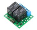
Pololu - Side-by-side comparison of the single and dual versions of the Pololu basic SPDT relay carriers
Our basic relay carrier boards are available in single-channel and dual-channel versions. The single-relay carrier is less than half the size of the 2-channel carrier (due in part to its smaller mounting holes and lack of barrel jack footprints), so it might be more appropriate to use two single-channel boards instead of one 2-channel board in some space-constrained applications. The following table shows some of the key differences between the two versions:
| Voltage options | Board size | Mounting hole size | # of channels | DC power jack option | |
|---|---|---|---|---|---|
| Single-relay carrier | 5 V and 12 V | 1.15″ × 1″ | 0.086″ (#2 or M2) | 1 | no |
| Dual-relay carrier | 5 V and 12 V | 1.5″ × 1.8″ | 0.125″ (#4 or M3) | 2 | yes |

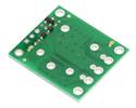
Pinout of Pololu basic SPDT relay carrier for “sugar cube” relays
The switch portion of the relay is accessible on one side of the board while the control pins are routed to the other. The relay coil is powered by supplying 5 V or 12 V across the VDD and GND pins (depending on the relay), and it is activated by a digital high control signal on the EN pin. The control signal is fed directly to a BSS138 N-channel MOSFET, which in turn actuates the relay coil when the signal voltage exceeds approximately 2.5 V (see BSS138 datasheet (92k pdf) for details).
The relay switch terminals COM (common), NO (normally open), and NC (normally closed) are routed on the PCB with a minimum clearance of 60 mils (1.5 mm) from other copper. The copper traces are designed to be at least 45 mil (1.1 mm) from the board edges, though manufacturing variations in the board edges can make those distances slightly lower.
In most applications, the current and voltage ratings for the module will match the ratings of the relay used. Maximum current, maximum voltage, and life expectancy are interdependent; we therefore recommend careful examination of your relay’s datasheet.
Warning: This product is not designed to or certified for any particular high-voltage safety standard. Working with voltages above 30 V can be extremely dangerous and should only be attempted by qualified individuals with appropriate equipment and protective gear.
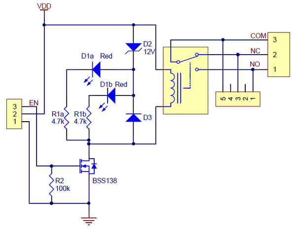 |
| Schematic diagram for the Pololu basic SPDT relay carrier. |
|---|
This schematic is also available as a downloadable pdf (131k pdf).
| Size: | 1″ × 1.15″ × 0.1″1 |
|---|---|
| Weight: | 16 g |
| Voltage: | 12 V |
|---|---|
| Partial kit?: | Y |