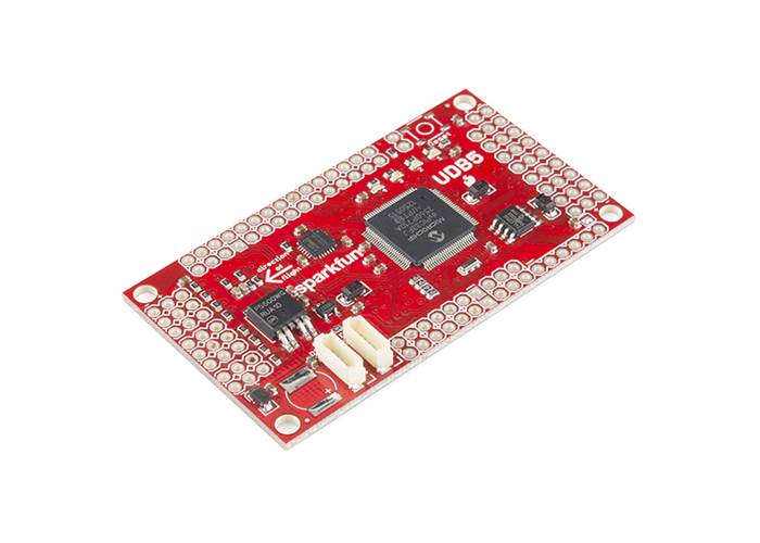
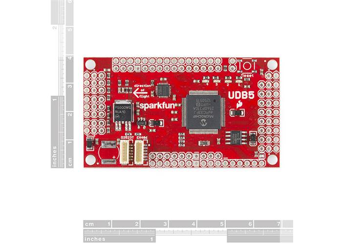
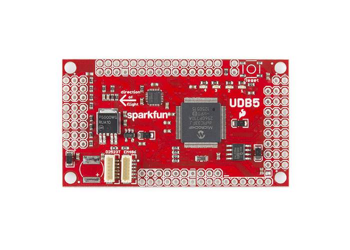
Our UAV Development Board is back! The UDB5 (UAV Development Board version 5) comes populated with a dsPIC33FJ256 CPU, and the impressive MPU-6000, a MEMS 3-axis gyroscope and 3-axis accelerometer. The on-board Invensense gyro even has enough vibration tolerance to be used in RC heli applications.
Our UAV Development Board is back! The UDB5 (UAV Development Board version 5) comes populated with a dsPIC33FJ256 CPU, and the impressive MPU-6000, a MEMS 3-axis gyroscope and 3-axis accelerometer. The on-board Invensense gyro even has enough vibration tolerance to be used in RC heli applications.
By itself, the board can be used to develop a three axis IMU controller. By addition of an EM406 or D2523T GPS receiver, it can be used to develop a UAV controller for an RC car, plane, helicopter, or boat. It comes with self-testing firmware that can serve as a starting point for you to develop your own control and navigation firmware. There is even fully functional, open source autopilot firmware available. We’ve made a few changes with the UDB5, we’ve removed the MMA7361 three axis accelerometer, the dual axis IDG500 gyro, and the single axis ISZ500 gyro and moved to an MPU-6000. The PCB form factor hasn’t changed. If you like, you can add a reset button and/or a 0.2F super cap.
Note: For programming, we recommend the PICkit3. Check the related products below.
Note: A GPS module is not included. Check the related products below.
Features:
Replaces:GPS-11115