The Pololu Dual VNH2SP30 Motor Driver Carrier MD03A is compact motor driver capable of delivering continuous 14A per output channel with a peak of 30 per channel and a PWM frequency of 20kHz. It operates over 5.5V - 16V and includes reverse voltage protection. Great for mid-sized robots.
If you are looking to drive two high-power motors through one compact unit, these dual VNH2SP30 motor driver carriers are perfect for you. With these boards, it’s easy to get a medium-sized, differential drive robot running in no time. The VNH2 version is a higher powered version than its VNH3 counterpart.
 The Pololu dual high-power motor drivers are compact carriers for the VNH3SP30 and VNH2SP30 motor driver integrated circuits from ST. The board incorporates most of the components of the typical application diagram on page 8 of the VNH2SP30 datasheet, including pull-up and current-limiting resistors and a FET for reverse battery protection. (The current sense circuit is populated on both versions of the board, but only the VNH2SP30 supports current sense.) To keep the number of I/O lines down, the two enable/diagnostic lines on each chip are tied together. All you need to add is a microcontroller or other control circuit to turn the H-Bridges on and off.
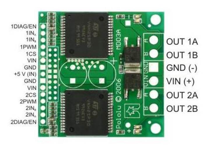
 In a typical application, the power connections are made on one end of the board, and the control connections are made on the other end. +5 volts must be supplied to the board through the smaller 0.1"-spaced pins; the input voltage is available at those pins as well, but the connection is not intended for currents exceeding a few amps. The diagnostic pins can be left disconnected if you do not want to monitor the fault conditions of the motor drivers. INA and INB control the direction of each motor, and the PWM pins turns the motors on or off. For the VNH2SP30 version, the current sense (CS) pins will output approximately 0.13 volts per amp of output current but do not on this VNH3SP30.
The dual motor driver PCB includes provisions for installing up to three large capacitors to limit disturbances on the main power line. Two 10mm radial capacitors may be mounted between the motor driver ICs, and an axial capacitor may be mounted between the ICs and power connections. It is generally not necessary to use all three capacitors; two radial capacitors are included with each unit. For applications that require a low profile, a single capacitor can be installed on its side as shown in the picture below.
 |
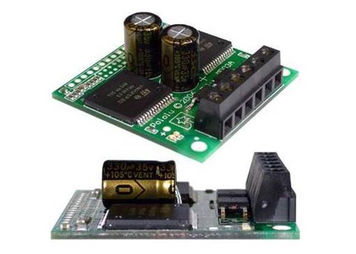 |
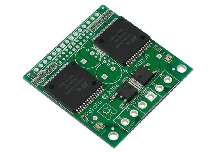
| VNH2SP30 carrier board as it comes in the packet | VNH2SP30 carrier board capacitor mounting options |
Note: A 15-pin male header, three 2-pin terminal blocks, and two electrolytic capacitors are included but not soldered onto the boards. No printed documentation is shipped with these items; please see the VNH3SP30 and VNH2SP30 datasheets linked under the Resources tab.
The motor drivers have maximum current ratings of 30 A continuous. However, the chips by themselves will overheat at lower currents (see table above for typical values). The actual current you can deliver will depend on how well you can keep the motor drivers cool. The carrier printed circuit board is designed to draw heat out of the motor driver chips, but performance can be improved by adding a heat sink. In our tests, we were able to deliver short durations (on the order of milliseconds) of 30 A and several seconds of 20 A without overheating. At 6 A, the chip gets just barely noticeably warm to the touch. For high-current installations, the motor and power supply wires should also be soldered directly instead of going through the supplied terminal blocks, which are rated for up to 15 A.
Many motor controllers or speed controllers can have peak current ratings that are substantially higher than the continuous current rating; this is not the case with these motor drivers, which have a 30 A continuous rating and a over-current protection that can kick in as low as 30 A (45 A typical). Therefore, the stall current of your motor should not be more than 30 A. (Even if you expect to run at a much lower average current, the motor can still draw high currents when it is starting or if you use low duty cycle PWM to keep the average current down.)
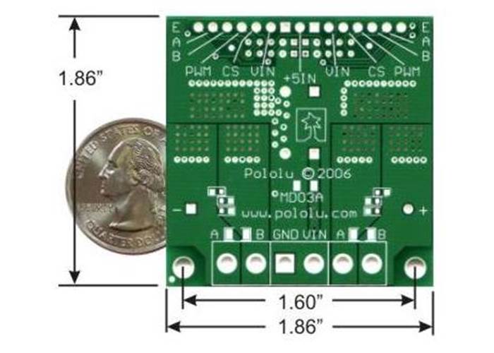
| Size: | 1.86" x 1.86" / 47.2mm x 47.2mm |
| Motor driver: | VNH2SP30 |
| Motor channels: | 2 |
| Minimum operating voltage: | 5.5 V |
| Maximum operating voltage: | 16 V(1) |
| Continuous output current per channel: | 14 A |
| Peak output current per channel: | 30 A |
| Continuous paralleled output current: | 25 A |
| Maximum PWM frequency: | 20 kHz |
| Reverse voltage protection?: | Y(1) |
| VNH3SP30 | VNH2SP30 | |
| MOSFET on-resistance (per leg) | 34 mΩ | 19 mΩ |
| Maximum PWM frequency | 10 kHz | 20 kHz |
| Current sense | none | approximately 0.13 volts per amp |
| Over-voltage shutoff | none (operates up to 30 V) | could be as low as 16 V (19 V typical) |
| Time to overheat at 20 A* | 8 seconds | 35 seconds |
| Time to overheat at 15 A* | 30 seconds | 150 seconds |
| Current for infinite run time* | 9 A | 14 A |

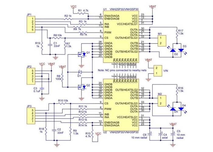
Pololu VNH3SP30 Dual High Current Motor Driver Carrier Schematic
(Click for a big picture)