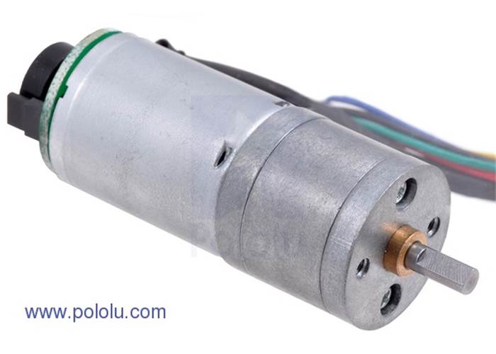
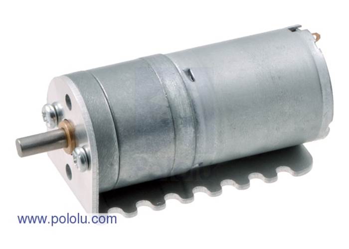
This gearmotor uses a motor with extra-strong magnets and a 75:1 metal gearbox to deliver a lot of power in a relatively small package. It has an integrated 48 CPR quadrature encoder, which provides 3592 counts per revolution of the gearbox’s output shaft. These units have a 4 mm-diameter D-shaped output shaft. Key specs at 6 V: 75 RPM and 80 mA free-run, 85 oz-in (6.1 kg-cm) and 2.2 A stall.
These motors are intended for use at 6 V. In general, these kinds of motors can run at voltages above and below this nominal voltage, so they should comfortably operate in the 3 – 9 V range, though they can begin rotating at voltages as low as 1 V. Higher voltages could start negatively affecting the life of the motor.
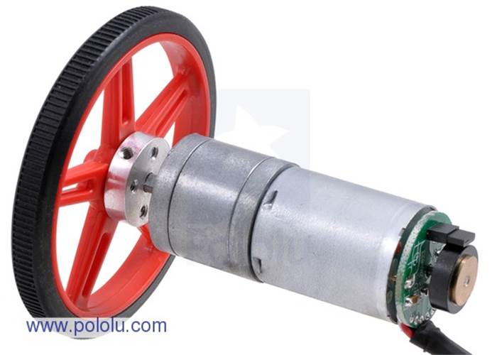
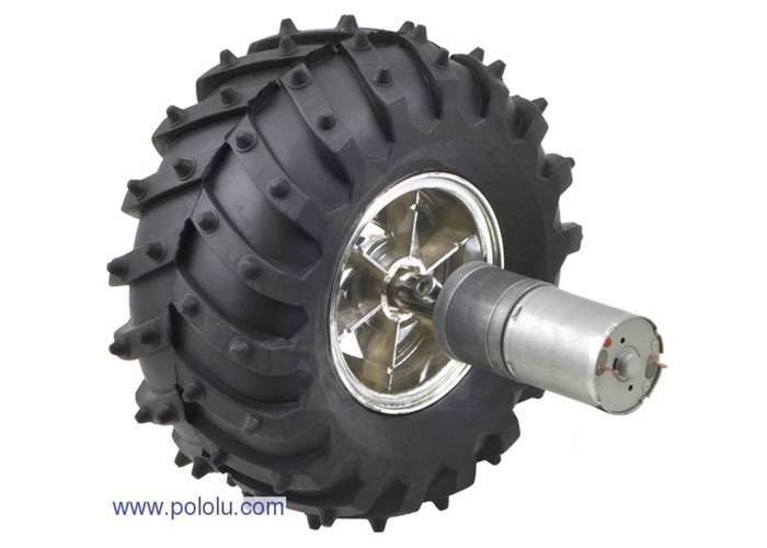
These gearmotors have output shafts with a diameter of 4 mm. The Pololu universal aluminum mounting hub for 4mm shafts can be used to mount our larger Pololu wheels (60mm-, 80mm -diameter) or custom wheels and mechanisms to the gearmotor’s output shaft (see the left picture below).
We also stock Pololu's 25D Metal Gearmotor Bracket Pair that fits these motors.
The gearbox’s output shaft works directly with the 120mm-diameter Wild Thumper wheels.
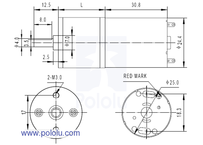
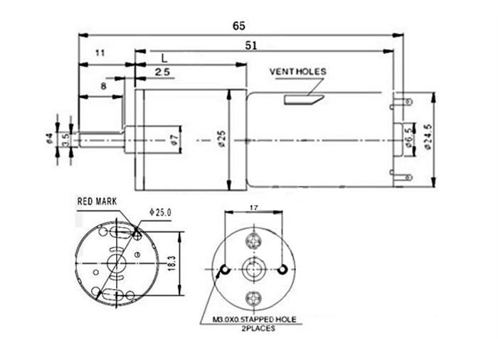
The face plate has two mounting holes threaded for M3 screws.
The diagram below shows the dimensions (in mm) of the 25D mm line of gearmotors. The value of 'L' is 21mm for this motor.
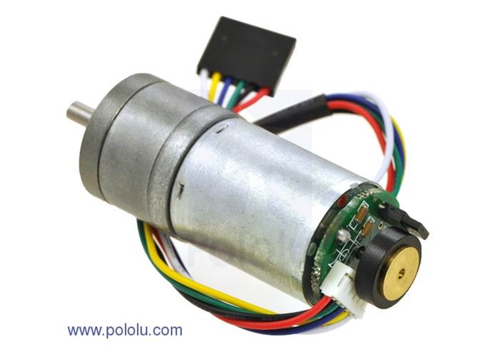
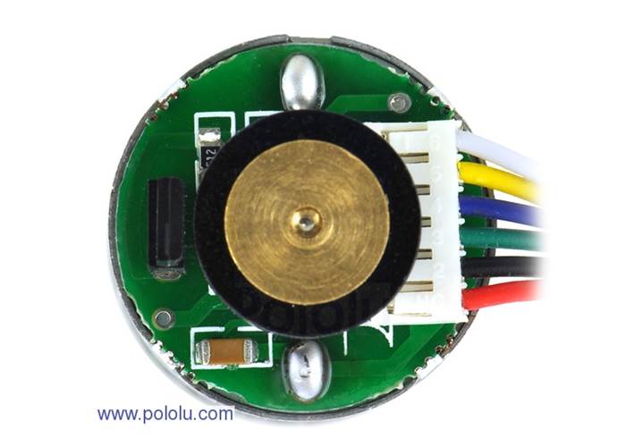
A two-channel Hall effect encoder is used to sense the rotation of a magnetic disk on a rear protrusion of the motor shaft. The quadrature encoder provides a resolution of 48 counts per revolution of the motor shaft. To compute the counts per revolution of the gearbox output, multiply the gear ratio by 48. The motor/encoder has six color-coded, 11" (28 cm) leads:
| Colour | Function |
| Red | motor power (connects to one motor terminal) |
| Black | motor power (connects to the other motor terminal) |
| Green | encoder GND |
| Blue | encoder Vcc (3.5 – 20 V) |
| Yellow | encoder A output |
| White | encoder B output |
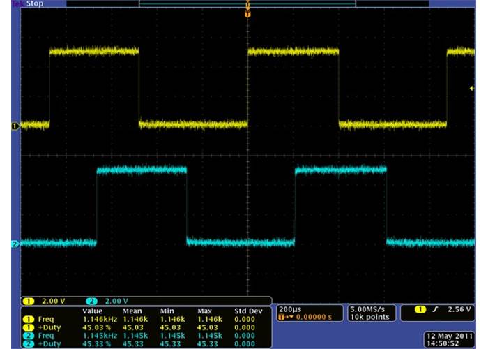
The Hall sensor requires an input voltage, Vcc, between 3.5 and 20 V and draws a maximum of 10 mA. The A and B outputs are square waves from 0 V to Vcc approximately 90° out of phase. The frequency of the transitions tells you the speed of the motor, and the order of the transitions tells you the direction. The following oscilloscope capture shows the A and B (yellow and white) encoder outputs using a motor voltage of 6 V and a Hall sensor Vcc of 5 V:
|
|
| Encoder A and B outputs for 25D mm LP metal gearmotor with 48 CPR encoder (motor running at 6 V). |
By counting both the rising and falling edges of both the A and B outputs, it is possible to get 48 counts per revolution of the motor shaft. Using just a single edge of one channel results in 12 counts per revolution of the motor shaft, so the frequency of the A output in the above oscilloscope capture is 12 times the motor rotation frequency.
| Size: | 25D x 54L mm |
|---|---|
| Weight: | 100g |
| Shaft diameter: | 4 mm |
| Gear ratio: | 75:1 |
|---|---|
| Free-run speed @ 6V: | 75 rpm |
| Free-run current @ 6V: | 80 mA |
| Stall current @ 6V: | 2200 mA |
| Stall torque @ 6V: | 6.1 kg/cm |