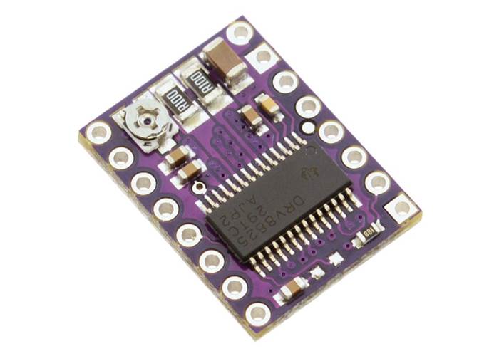
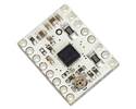
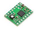
The DRV8825 stepper motor driver carrier V2 is a breakout board for TI’s DRV8825 microstepping bipolar stepper motor driver. The DRV8825 features adjustable current limiting, overcurrent and overtemperature protection, and six microstep resolutions (down to 1/32-step). Operates from 8.2V - 45V and delivers 1.5A per phase without a heat sink. 2.2A with cooling.
In stock in Australia
Shipping from $2.90
+131 more from our supplier in 7-10 days
Our Code: MCU-60105
Supplier Link: [Pololu MPN:2133]
This product is a carrier board or breakout board for TI’s DRV8825 stepper motor driver; we therefore recommend careful reading of the DRV8825 datasheet (1MB pdf) before using this product. This stepper motor driver lets you control one bipolar stepper motor at up to 2.2 A output current per coil (see the Power Dissipation Considerations section below for more information). Here are some of the driver’s key features:
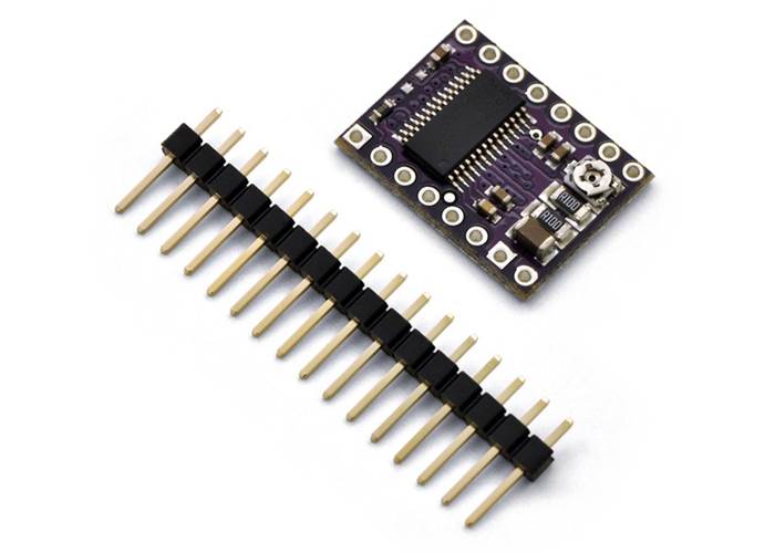
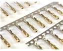
The DRV8825 stepper motor driver carrier ships with one 1×16-pin breakaway 0.1" male header. The headers can be soldered in for use with solderless breadboards or 0.1" female connectors. You can also solder your motor leads and other connections directly to the board.

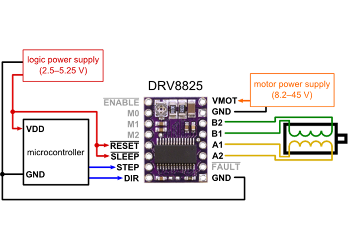
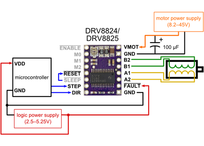
The driver requires a motor supply voltage of 8.2 – 45 V to be connected across VMOT and GND. This supply should have appropriate decoupling capacitors close to the board, and they should be capable of delivering the expected currents.
Four, six, and eight-wire stepper motors can be driven by the DRV8825 if they are properly connected; a FAQ answer explains the proper wirings in detail.
Stepper motors typically have a step size specification (e.g. 1.8° or 200 steps per revolution), which applies to full steps. A microstepping driver such as the DRV8825 allows higher resolutions by allowing intermediate step locations, which are achieved by energizing the coils with intermediate current levels. For instance, driving a motor in quarter-step mode will give the 200-step-per-revolution motor 800 microsteps per revolution by using four different current levels.
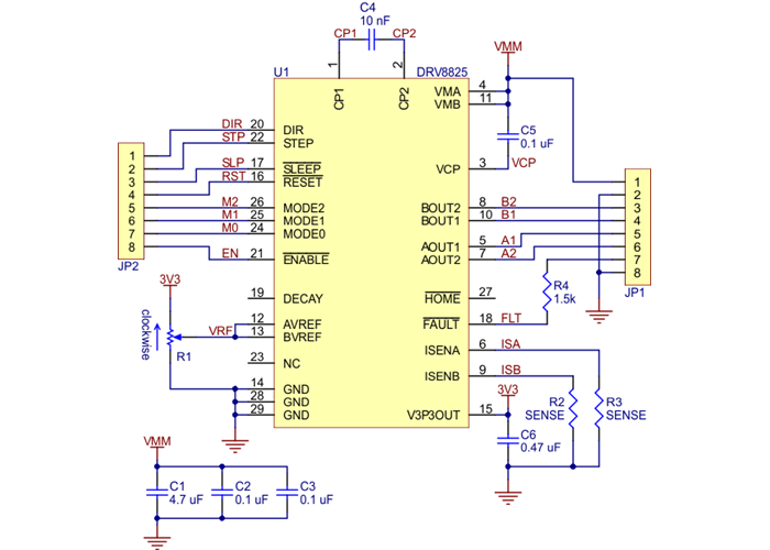
The resolution (step size) selector inputs (MODE0, MODE1, and MODE2) enable selection from the six step resolutions according to the table below. All three selector inputs have internal 100kΩ pull-down resistors, so leaving these three microstep selection pins disconnected results in full-step mode. For the microstep modes to function correctly, the current limit must be set low enough (see below) so that current limiting gets engaged. Otherwise, the intermediate current levels will not be correctly maintained, and the motor will skip microsteps.
| MODE0 | MODE1 | MODE2 | Microstep Resolution |
|---|---|---|---|
| Low | Low | Low | Full step |
| High | Low | Low | Half step |
| Low | High | Low | 1/4 step |
| High | High | Low | 1/8 step |
| Low | Low | High | 1/16 step |
| High | Low | High | 1/32 step |
| Low | High | High | 1/32 step |
| High | High | High | 1/32 step |
Each pulse to the STEP input corresponds to one microstep of the stepper motor in the direction selected by the DIR pin. These inputs are both pulled low by default through internal 100kΩ pull-down resistors. If you just want rotation in a single direction, you can leave DIR disconnected.
The chip has three different inputs for controlling its power states: RESET, SLEEP, and ENBL. For details about these power states, see the datasheet. Please note that the SLEEP pin is pulled low by default through a 1MΩ pull-down resistor, and the RESET and ENBL pins are both pulled low by default through internal 100kΩ pull-down resistors. This means that RESET and SLEEP will be preventing the driver from operating if left disconnected. Both of these pins must be pulled high to enable the driver (they can be connected directly to a logic “high” voltage between 2.2 and 5.25 V, or they can be dynamically controlled via connections to digital outputs of an MCU). The default state of the ENBL pin is to enable the driver, so this pin can be left disconnected.
The DRV8825 also features a FAULT output that drives low whenever the H-bridge FETs are disabled as the result of over-current protection or thermal shutdown. Otherwise, the pin is floating, so you will need to use a pull-up resistor to give it a default high state if you want to use this pin. Note that there is a 1.5k protection resistor in series with the pin that you should take into account when selecting your pull-up resistor (i.e. it should probably be at least 10k). This 1.5k series resistor means it is safe to connect this pin to a logic high voltage, as might happen if you use this board in a system designed for the pin-compatible A4988 carrier.
To achieve high step rates, the motor supply is typically much higher than would be permissible without active current limiting. For instance, a typical stepper motor might have a maximum current rating of 1 A with a 5Ω coil resistance, which would indicate a maximum motor supply of 5 V. Using such a motor with 12 V would allow higher step rates, but the current must actively be limited to under 1 A to prevent damage to the motor.
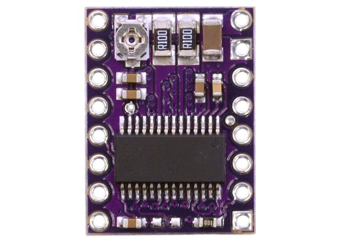
The DRV8825 supports such active current limiting, and the trimmer potentiometer on the board can be used to set the current limit. One way to set the current limit is to put the driver into full-step mode and to measure the current running through a single motor coil without clocking the STEP input. The measured current will be 0.7 times the current limit (since both coils are always on and limited to approximately 70% of the current limit setting in full-step mode).
Another way to set the current limit is to measure the voltage on the “ref” pin and to calculate the resulting current limit (the current sense resistors are 0.100Ω). The ref pin voltage is accessible on a via that is circled on the bottom silkscreen of the circuit board. The current limit relates to the reference voltage as follows:
Current Limit = VREF * 2
So, for example, if the reference voltage is 0.5 V, the current limit is 1 A. As mentioned above, in full step mode, the current through the coils is limited to 70% of the current limit, so to get a full-step coil current of 1.5 A, the current limit should be 1.5 A/0.7=2.1 A, which corresponds to a VREF of 2.1 A/2=1.05 V. See the DRV8825 datasheet for more information.
The DRV8825 driver IC has a maximum current rating of 2.5 A per coil, but the current sense resistors further limit the maximum current to 2.2 A, and the actual current you can deliver depends on how well you can keep the IC cool. The carrier’s printed circuit board is designed to draw heat out of the IC, but to supply more than approximately 1.5 A per coil, a heat sink or other cooling method is required.
Please note that measuring the current draw at the power supply will generally not provide an accurate measure of the coil current. Since the input voltage to the driver can be significantly higher than the coil voltage, the measured current on the power supply can be quite a bit lower than the coil current (the driver and coil basically act like a switching step-down power supply). Also, if the supply voltage is very high compared to what the motor needs to achieve the set current, the duty cycle will be very low, which also leads to significant differences between average and RMS currents. Additionally, please note that the coil current is a function of the set current limit, but it does not necessarily equal the current limit setting. For example, in full-step mode, the coil current is internally limited to 70% of the set maximum, so you would set the current limit to around 2.1 A to get a coil current of 1.5 A.

The SENSE resistors R2 and R3 are 0.100 Ω on this version of the DRV8825 carrier.
The DRV8825 carrier was designed to be as similar to our A4988 stepper motor driver carriers as possible, and it can be used as a drop in replacement for the A4988 carrier in many applications because it shares the same size, pinout, and general control interface. There are a few differences between the two modules that should be noted, however:
In summary, the DRV8825 carrier is similar enough to our A4988 carriers that the minimum connection diagram for the A4988 is a valid alternate way to connect the DRV8825 to a microcontroller as well:
DRV8825 alternate wiring diagram
File downloads
Texas Instruments DRV8825 stepper motor driver datasheet (1MB pdf)
Yes. To avoid damaging your stepper motor, you want to avoid exceeding the rated current, which is 600 mA in this instance. The DRV8825 stepper motor drivers let you limit the maximum current, so as long as you set the limit below the rated current, you will be within spec for your motor, even if the voltage exceeds the rated voltage. The voltage rating is just the voltage at which each coil draws the rated current, so the coils of your stepper motor will draw 600 mA at 3.9 V. By using a higher voltage along with active current limiting, the current is able to ramp up faster, which lets you achieve higher step rates than you could using the rated voltage.
Measuring the current draw at the power supply does not necessarily provide an accurate measure of the coil current. Since the input voltage to the driver can be significantly higher than the coil voltage, the measured current on the power supply can be quite a bit lower than the coil current (the driver and coil basically act like a switching step-down power supply). Also, if the supply voltage is very high compared to what the motor needs to achieve the set current, the duty cycle will be very low, which also leads to significant differences between average and RMS currents: RMS current is what is relevant for power dissipation in the chip but many power supplies won’t show that. You should base your assessment of the coil current on the set current limit or by measuring the actual coil currents.
Please note that while the DRV8825 driver IC is capable of supplying 2.5 A per coil, the chip by itself will overheat at lower currents. We have found that it generally requires a heat sink to deliver more than approximately 1.5 A per coil, but this number depends on factors such as ambient temperature and air flow. For example, sealing three DRV8825 driver carriers in close proximity in a small box will cause them to overheat at lower currents than a unit by itself in open air.
The answer to this question depends on the type of stepper motor you have. When working with stepper motors, you will typically encounter two types: unipolar stepper motors and bipolar stepper motors. Unipolar motors have two windings per phase, allowing the magnetic field to be reversed without having to reverse the direction of current in a coil, which makes unipolar motors easier to control than bipolar stepper motors. The drawback is that only half of the phase is carrying current at any given time, which decreases the torque you can get out of the stepper motor. However, if you have the appropriate control circuitry, you can increase the stepper motor torque by using the unipolar stepper motor as a bipolar stepper motor (note: this is only possible with 6- or 8-lead unipolar stepper motors, not with 5-lead unipolar stepper motors). Unipolar stepper motors typically have five, six, or eight leads.
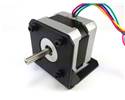
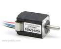
Bipolar steppers have a single coil per phase and require more complicated control circuitry (typically an H-bridge for each phase). The DRV8825 has the circuitry necessary to control a bipolar stepper motor. Bipolar stepper motors typically have four leads, two for each coil.
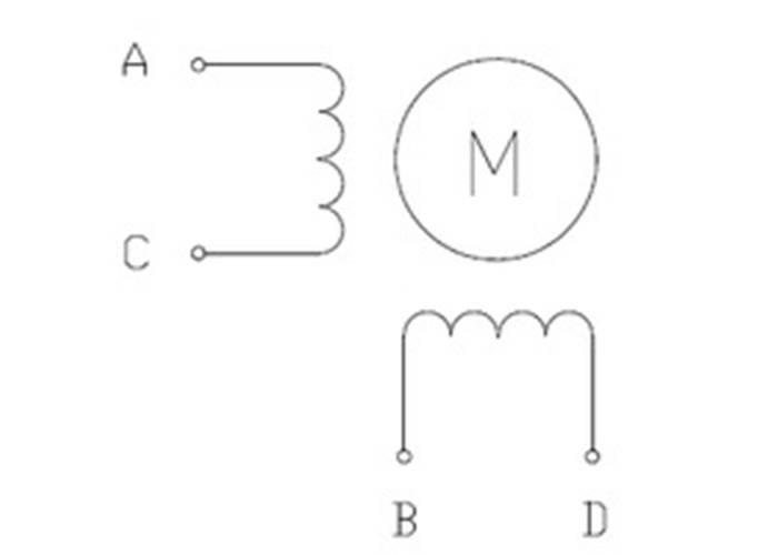
Two-phase bipolar stepper motor with four leads.
The above diagram shows a standard bipolar stepper motor. To control this with the DRV8825, connect stepper lead A to board output A1, stepper lead C to board output A2, stepper lead B to board output B1, and stepper lead D to board output B2. See the DRV8825 datasheet for more information.
If you have a six-lead unipolar stepper motor as shown in the diagram below:
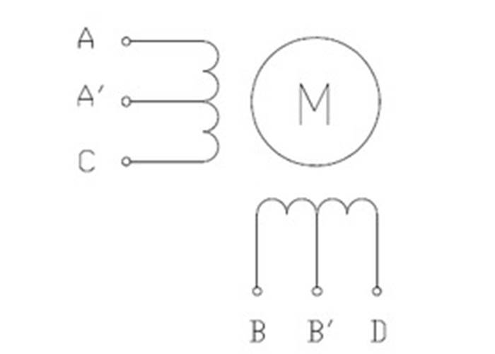
Two-phase unipolar stepper motor with six leads.
you can connect it to the DRV8825 as a bipolar stepper motor by making the bipolar connections described in the section above and leaving stepper leads A’ and B’ disconnected. These leads are center taps to the two coils and are not used for bipolar operation.
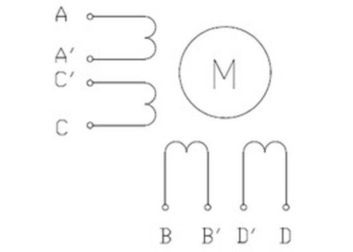
If you have an eight-lead unipolar stepper motor as shown in the diagram below:

Two-phase unipolar stepper motor with eight leads.
you have several connection options. An eight-lead unipolar stepper motor has two coils per phase, and it gives you access to all of the coil leads (in a six-lead unipolar motor, lead A’ is internally connected to C’ and lead B’ is internally connected to D’). When operating this as a bipolar stepper, you have the option of using the two coils for each phase in parallel or in series. When using them in parallel, you decrease coil inductance, which can lead to increased performance if you have the ability to deliver more current. However, since the DRV8825 actively limits the output current per phase, you will only get half the phase current flowing through each of the two parallel coils. When using them in series, it’s like having a single coil per phase (like in four-lead bipolar steppers or six-lead unipolar steppers used as bipolar steppers). We recommend you use a series connection.
To connect the phase coils in parallel, connect stepper leads A and C’ to board output A1, stepper leads A’ and C to board output A2, stepper leads B and D’ to board output B1, and stepper leads B’ and D to board output B2.
To connect the phase coils in series, connect stepper lead A’ to C’ and stepper lead B’ to D’. Stepper leads A, C, B, and D should be connected to the stepper motor driver as normal for a bipolar stepper motor (see the bipolar stepper connections above).